2-3
3.
Connect the Power Cord
– Connect the power adapter to the access point,
and the power cord to an AC power outlet.
Note:
If the access point is connected to both a PoE source device and an AC power
source, PoE will be disabled.
Caution:
Use ONLY the power adapter supplied with this access point. Otherwise, the
product may be damaged.
4.
Observe the Self Test
– When you power on the access point, verify that the
Power indicator stops flashing and remains on, and that the other indicators
start functioning as described under “LED Indicators” on page 1-4. If the Power
LED turns on amber, the self test has not completed correctly. Refer to
“Troubleshooting” on page A-1.
5.
Connect the Ethernet Cable
– The access point can be wired to a
10/100 Mbps Ethernet through a network device such as a hub or a switch.
Connect your network to the RJ-45 port on the back panel with category 3, 4, or
5 UTP Ethernet cable. When the access point and the connected device are
powered on, the WAN LED should turn on indicating a valid network
connection. If the WAN LED fails to turn on refer to
“Troubleshooting” on page A-1.
D
C
5
V
W
A
N
R
e
s
e
t
A
N
T
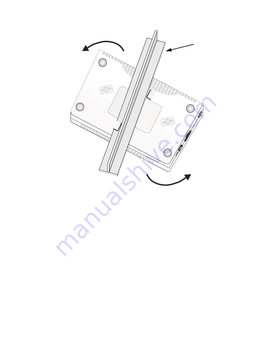
T-rail (ceiling mount)
Summary of Contents for EAP2316A
Page 1: ...www edge core com Installation Guide Powered by Accton EAP2316A 2 4 GHz Wireless Access Point...
Page 2: ......
Page 4: ...EAP2316A E072005 R01...
Page 8: ...iv...
Page 10: ...vi Contents...
Page 16: ...Introduction 1 6...
Page 28: ...Troubleshooting A 2...
Page 32: ...Cables and Pinouts B 4...
Page 37: ......
Page 38: ...Model Number EAP2316A Pub Number 150200023800E E072005 R01...


