Quick Start Guide
– 2 –
Mount the Switch
Ground the Switch
Warning:
For a safe and reliable installation, use only
the accessories and screws provided with the AS9926-
24D. Use of other accessories and screws could result in
damage to the unit. Any damages incurred by using
unapproved accessories are not covered by the warranty.
Avertissement:
Pour une installation sûre et fiable,
utilisez uniquement les accessoires et les vis fournies avec
le AS9926-24D. L’utilisation d’autres accessoires et vis
pourrait endommager l’appareil. Les dommages causés
par l’utilisation d’accessoires non approuvés ne sont pas
couverts par la garantie.
Caution:
The switch includes plug-in power supply (PSU) and
fan tray modules that are installed into its chassis. Make sure all
installed modules have a matching airflow direction (front-to-
back or back-to-front).
Attention:
Le commutateur comprend des modules
d’alimentation et de modules de ventilation installés dans son
châssis. Assurez-vous que tous les modules installés ont une
direction d’air adaptée (avant-arrière ou arrière-arrière).
Note:
The switch has the Open Network Install Environment
(ONIE) software installer preloaded on the switch, but no switch
software image. Information about compatible switch software
can be found at
www.edge-core.com
.
Note:
The drawings in this document are for illustration only
and may not match your particular model.
Caution:
This device must be installed in a
telecommunications room or a server room.
Attention:
Cet appareil doit être installé dans une salle de
télécommunication ou une salle de serveur.
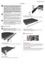
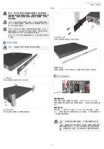
1
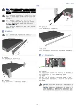
1. Attach the Brackets
Use the included screws to attach the front- and rear-post brackets.
2. Mount the Switch
Mount the switch in the rack and secure it with rack screws.
3. Lock the Rear-Post Brackets
Use the included screws to lock the position of the rear-post brackets.
Optional Slide-Rail Installation
An optional slide-rail kit is available for rack installation. Follow the
installation procedure provided with the kit.
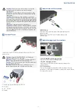
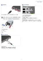
2
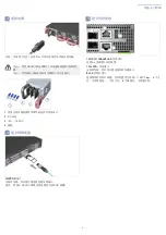
Verify Rack Ground
Ensure the rack on which the switch is to be mounted is properly
grounded and in compliance with ETSI ETS 300 253. Verify that there is
a good electrical connection to the grounding point on the rack (no
paint or isolating surface treatment).
Attach Grounding Wire
Attach a lug (not provided) to a #12 AWG minimum grounding wire
(not provided), and connect it to the grounding point on the switch rear
panel. Then connect the other end of the wire to rack ground.
Installation


