The Subsea Bottle
Connectors
Umbilical
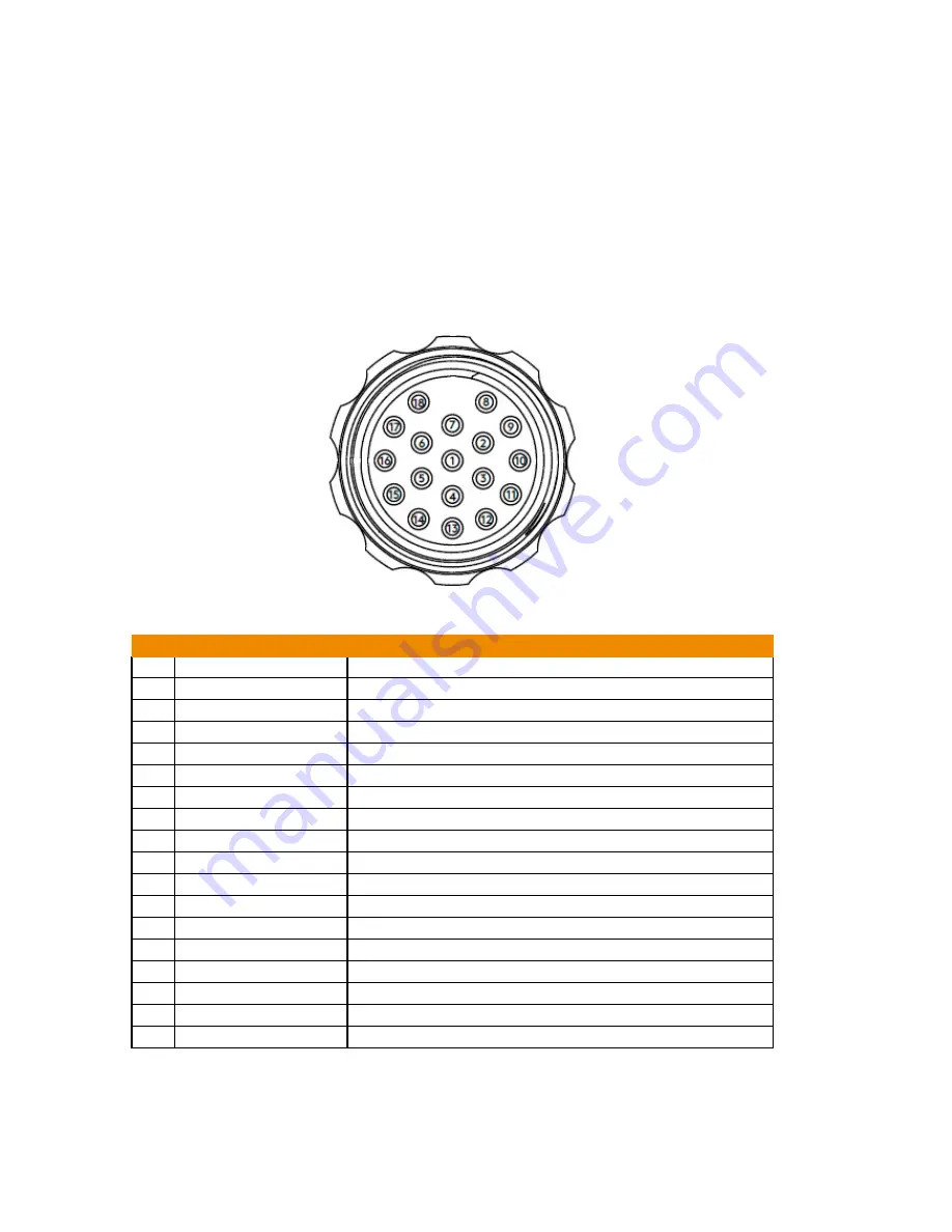
The umbilical connector carries power and communications between the subsea unit and
topside unit. It is a wet-mateable subsea connector which is designed to be made and broken
in wet conditions topside. It should not be disconnected subsea.
The deck integration cable can be connected directly to this connector to test and configure the
system before an umbilical or subsea whip is connected for deployment subsea. Ensure that the
orientation of the missing pin is correctly aligned when mating the plug and socket. If the
connectors are mis-aligned and the connection is forced together then damage may occur to
the plug, socket or whole unit.
Figure 2-3
Umbilical connector
Pinout
Pin
Signal
Description
1
Drain wire
Drain Wire
2
Extended Ethernet -
Communication over 450 meters
3
Extended Et
Communication over 450 meters
4
ETH_RX-
Ethernet Rx-. Available on R model only.
5
Ethernet Rx+. Available on R model only.
6
ETH_TX-
Ethernet Tx-. Available on R model only.
7
Ethernet Tx+. Available on R model only.
8
RS485TX- or RS232_RTS
RS-485 Tx or RS-232 RTS signal. Available on R model only.
9
or RS232_TX
RS-485 Tx+ or RS-232 CTS signal. Available on R model only.
10
RS485_RX- or RS232_CTS
RS-485 Rx- or RS-232 CTS signal. Available on R model only.
11
R or RS232_RX
RS-485 Rx+ or RS232 Rx signal. Available on R model only.
12
RS232_GND
Ground for RS232 communication. Available on R model only.
13
nSAFE_BOOT
Signal active low to boot the system in recovery mode.
14
V-
External power supply GND
15
V-
External power supply GND
16
V+
External positive power supply, nominal voltage input is 48Vcc
17
V+
External positive power supply, nominal voltage input is 48Vcc
18
GNDC
Chassis Ground for cable overall shield and drain wire
Summary of Contents for TSC U41
Page 1: ...Getting Started with TSC U41 Modernizing Subsea ACFM User s Manual ...
Page 7: ...General Precautions and Conventions ...
Page 13: ...Chapter 1 System Overview ...
Page 27: ...Chapter 2 The Subsea Bottle ...
Page 33: ...Chapter 3 The Topside Unit ...
Page 40: ...Chapter 4 Assist3 Software ...
Page 67: ...Assist3 Software 55 Figure 4 37 Finishing the installation ...
Page 69: ...Chapter 5 Troubleshooting ...
Page 71: ...Troubleshooting 59 ...


