Inuktun Services Ltd.
2569 Kenworth Road, Suite C
Nanaimo, BC, V9T 3M4
CANADA
+1.250.729.8080
[email protected]
www.eddyfitechnologies.com
2569 Kenworth Road, Suite C
Nanaimo, BC, V9T 3M4
CANADA
+1.250.729.8080
[email protected]
www.eddyfitechnologies.com
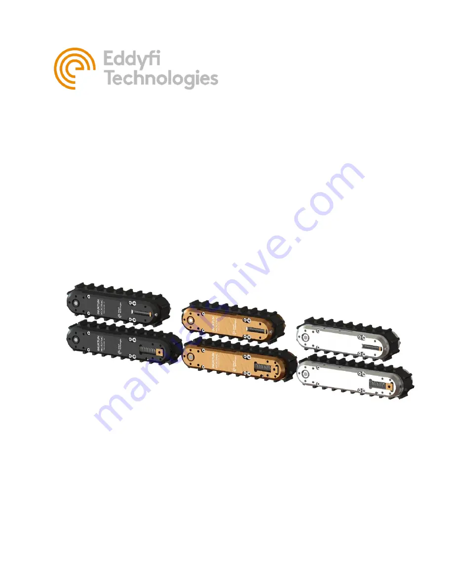
INUKTUN
MICROTRAC™


