Chapter 5 — Techniques
79
Chart software on Windows computers
To switch to the Galvanostat mode of operation, choose the Potentiostat
command in the Channel Function pop-up menu to open the control
window, and turn on the Galvanostat and Dummy radio buttons,
When in Galvanostat mode, the current and potential signals will be
reversed from normal (potentiostatic) operation. That is, the ‘I Out’
cable will be carrying the potential signal (which will now appear on
Channel 1) and the ‘E Out’ cable the current signal (which will now
appear on Channel 2). You will need to configure the Units Conversion
of Channel 2 so as to ensure that the current signal is recorded in the
correct current units,
.
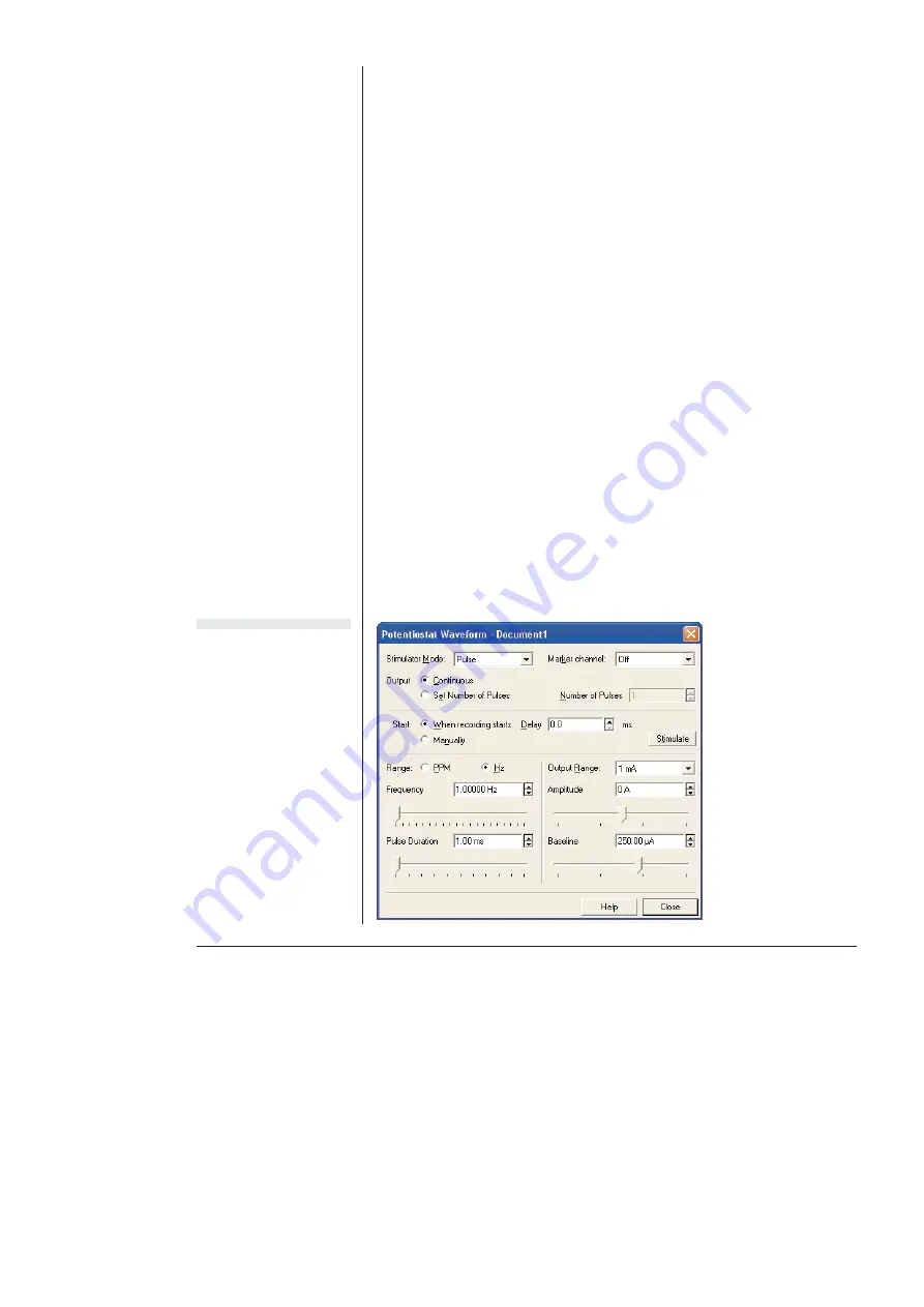
When the Chart Stimulator command (Setup menu) is selected it
accesses the Stimulator dialog box which, when using galvanostat
mode, allows a baseline and various current waveforms to be
configured,
.
Always select an appropriate current range for your system. While it is
possible to set an applied current of up to 100 mA, the Potentiostat/
Galvanostat cannot supply a potential much greater than ±10 V. Even
relatively small applied currents, with a highly resistive load, may
require potentials in excess of this. If in doubt, start with a small test
current and observe the resulting potential.
When in Galvanostat
mode the Stimulator
controls are used to
adjust the applied
current.Compare with
Potentiostat mode where
the Stimulator is used to
adjust applied potential,
Figure 5–19
The Chart Stimulator
dialog box when the
Potentiostat is in
Galvanostat mode
Summary of Contents for Picostat
Page 8: ...4 eDAQ Potentiostats ...
Page 28: ...24 eDAQ Potentiostats ...
Page 44: ...40 eDAQ Potentiostats ...
Page 64: ...60 eDAQ Potentiostats ...
Page 104: ...100 eDAQ Potentiostats ...
Page 112: ...108 eDAQ Potentiostats ...


