background image

32

eDAQ Potentiostats

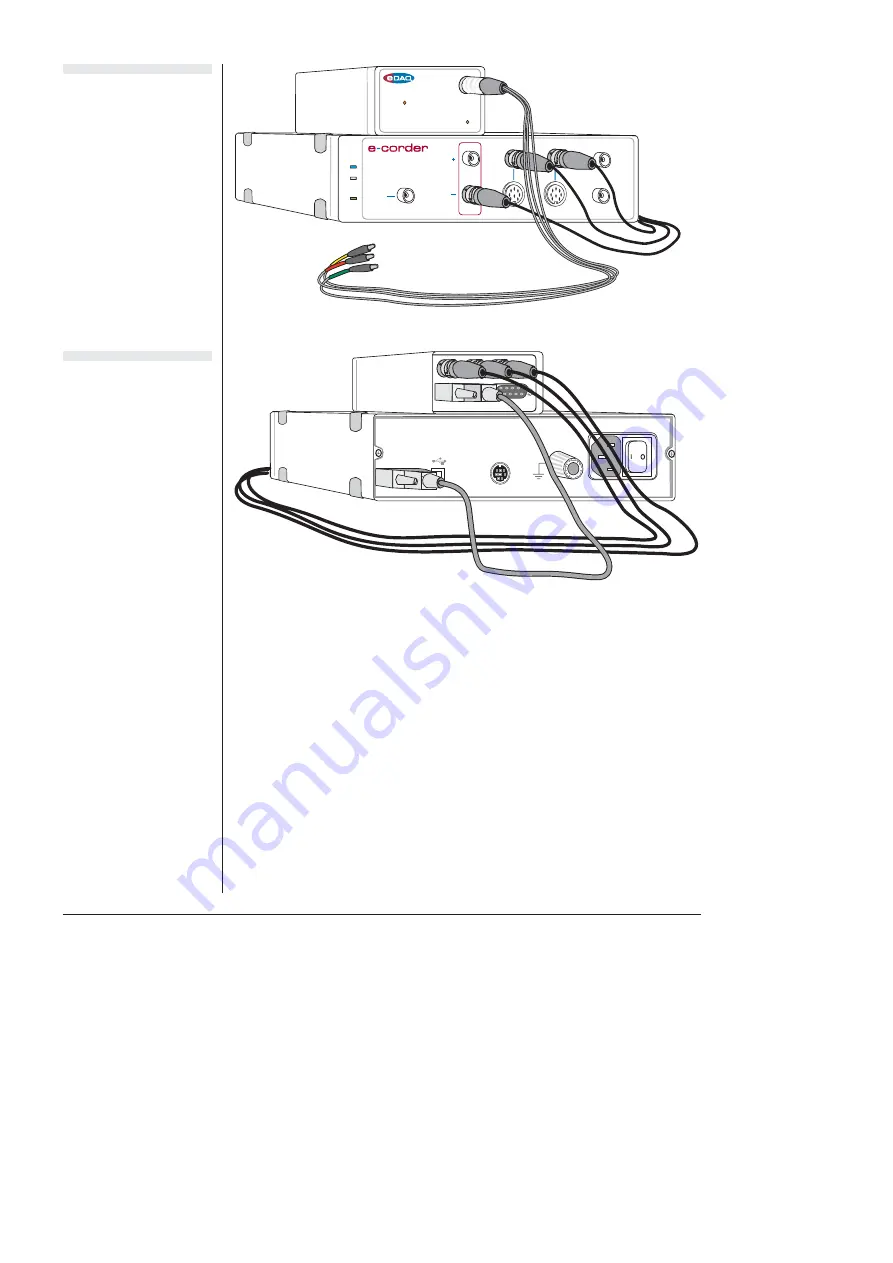
With these connections, when you use the software to set a more 
positive voltage, a more oxidising potential will be applied at the 
working electrode. Such an arrangement is shown in 

Figure 3–5

 and 

Figure 3–6

.

To operate the Picostat with the reverse polarity make the connections 
shown in 

Table 3–3

. With these connections, when you use the 

software to set a more positive voltage, a more reducing potential will 
be applied at the working electrode.

Check that all connectors are firmly attached. Loose connectors can 
cause erratic behaviour, or may cause the Picostat to fail to work. 

Output

Input 1

Input 3

Input 2

Input 4

Picostat

Overload

Trigger

Power

Status

401

Figure 3–6 

The Picostat shown 
connected to an 

e-corder

, back view.

Figure 3–5 

The Picostat shown 
connected to an 

e-corder

, front view.

Summary of Contents for Picostat

Page 1: ...der www eDAQ com eDAQ Potentiostats User Manual Potentiostat Picostat QuadStat Potentiostat Overload Picostat Overload WE WE WE WE QuadStat RE RE RE RE AE AE AE AE Channel 1 Channel 2 Channel 3 Channel 4 164 ...

Page 2: ...nd Scope are trademarks of ADInstruments Pty Ltd and are used under license by eDAQ EChem is a trademark of eDAQ Pty Ltd Other Trademarks Mac OS and Macintosh are registered trademarks of Apple Computer Inc Windows 98 Windows Me Windows 2000 and Windows XP are trademarks of Microsoft Corporation PostScript and Acrobat are registered trademarks of Adobe Systems Incorporated All other trademarks are...

Page 3: ...e Cable 27 The Online Indicator 27 The Overload Indicator 28 The Back Panel 29 E Out I Out and E In Connectors 29 I2 C Connectors 29 Grounding Connector 30 Connecting the Picostat 31 First Use 33 Picostat Control Window 35 Maintenance 39 4 The QuadStat 41 The Front Panel 42 Electrode Connectors 42 Electrode Cables 42 The Online Indicators 43 The Overload Indicators 43 The Back Panel 45 E Out I Out...

Page 4: ...t software on Macintosh 80 Scope software 82 Controlled Potential Electrolysis 82 Controlled Current Electrolysis 83 Amperometric Sensors 84 Biosensors 85 Microdialysis Sensor 86 Dissolved Oxygen dO2 Sensors 86 Nitric Oxide NO Sensors 87 A Technical Aspects 89 Potentiostat 89 Picostat 91 QuadStat 92 B Troubleshooting 95 C Specifications 101 Potentiostat 101 Picostat 104 QuadStat 106 D Electrochemi...

Page 5: ...ur channel three electrode potentiostat with gain ranges of 2 nA to 1 mA with current signal offset They are a part of the family of fully software controlled modular preamplifiers eDAQ Amps which are designed for use with the e corder system Some of the uses of the Potentiostat Picostat and QuadStat are mentioned in Chapter 5 and also in the EChem Software Manual which describes the use of the op...

Page 6: ...he Potentiostat Picostat and QuadStat are designed for performing voltammetric and amperometric experiments As with other eDAQ Amps they are designed to be operated under full software control and are automatically recognised by Chart Scope or EChem software which control their gain range signal filtering and other settings The eDAQ Amp family also include the pH Amp suitable for connection of pH ...

Page 7: ...g list are included and that there are no signs of damage that may have occurred during transit Contact your eDAQ distributor if you encounter a problem You should also become familiar with the basic features of your e corder system which are discussed in the e corder Manual which will be installed as a pdf file on your computer when you install the software ...

Page 8: ...4 eDAQ Potentiostats ...

Page 9: ...ct the Potentiostat Failure to do this may result in damage to the e corder and or the Potentiostat NEW FEATURES If you have used the older EA160 Potentiostat before then you will notice that the EA161 has new front and back panels and incorporates several new features iR compensation ZRA mode High Z mode and also has a High Stability option for stabilization of the Potentiostat in situations wher...

Page 10: ... from electrical interference noise pickup The pin assignments of the Potentiostat electrode connector are shown in Figure 2 2 The Auxiliary and Reference electrode leads have Potentiostat Overload Overload indicator light Electrode connector Lemo socket to electrodes Online indicator light Working Electrode Auxiliary Electrode Reference Electrode Reference Electrode Shield Working Electrode Shiel...

Page 11: ... the working green and auxiliary red leads to the two electrodes or circuit test points across which to measure the current page 16 The reference lead yellow can be connected to a reference electrode or circuit test point to measure the potential difference to the auxiliary and working leads When using High Z high impedance mode connect the working green lead to one electrode and the reference lea...

Page 12: ...mpensate by increasing the compliance potential that is the potential between the auxiliary and working electrodes If the compliance voltage exceeds specification about 11 V potential control of the cell is lost and drifting or oscillation of the signal can be seen Any data collected during this period is unreliable and should be discarded The Overload indicator will light as soon as there is an o...

Page 13: ...the e corder usually Output is used Reverse the polarity of the Potentiostat by using e corder Output E Out I Out E In Input Output I C Bus I C 2 BNC output connectors DB 9 pin I2C connectors 4 mm socket ground connection BNC input connector Digital Ground Regulated 17 V DC Regulated 8 V DC Regulated 17 V DC Power lines SCL DSC SDA DSD INT I2C control signals Digital Ground Regulated 17 V DC Regul...

Page 14: ...tiostat for this purpose The pin assignments are shown in Figure 2 4 The Output connector can be used for the attachment of other eDAQ Amps More information about the I2 C connector can be found in your e corder Manual Grounding Connector The Potentiostat back panel Figure 2 3 has a 4 mm grounding socket This enables connection of a Faraday cage with the green grounding cable included with the Pot...

Page 15: ...9 pin connectors at either end and three cables with BNC connectors at either end First make sure that the e corder is turned off Then connect the I2 C cable to the I2 C connector on the back panel of the e corder and the other the other end to the I2 C Input connector on the back panel of the Potentiostat Use the three BNC cables to connect the back panel of the Potentiostat to the front panel of...

Page 16: ...e a more reducing potential will be applied at the working electrode Check that all connectors are firmly attached Loose connectors can cause erratic behaviour or may cause the Potentiostat to fail to work Trigger Power Status Output Input 1 Input 3 Input 2 Input 4 401 Overload Potentiostat Figure 2 5 The Potentiostat shown connected to an e corder front view as described in Table 2 2 Figure 2 6 T...

Page 17: ... dialog box described in the Chart Software Manual and Scope Software Manual which are installed as pdf files in the eDAQ Documentation folder on your computer hard disk First Use After you have installed the software connected the e corder and computer as described with the booklet supplied with the e corder system and connected the Potentiostat as described above you are ready to begin When the ...

Page 18: ...so that an applied potential of 1 V should produce a current of 10 µA while other potential settings should produce corresponding currents Potentiostat Control Window With Chart software the Potentiostat Control window is accessed from the Potentiostat command in the Channel Function pop up menu Figure 2 7 shows the control window on a Windows computer and Figure Select low pass filter Select inpu...

Page 19: ...trode use connect the working green reference and auxiliary red leads appropriate electrodes or circuit test points The current signal is provided at I Out Figure 2 3 The potential signal is provided at E Out When two electrode potentiostat Select operating mode Select Potentiostat in the Channel pop up menu Signal display area Drag ticks and labels to adjust axis Pause Resume scrolling Axis expan...

Page 20: ...ference lead yellow lead to a reference electrode to measure the potential difference between the leads The high impedance potential signal is delivered at I Out The auxiliary lead red can be connected to a third electrode or test point to provide a ZRA current signal at E Out Figure 2 3 Please make sure the electrode lead wires are connected appropriately to your experiment before operating in an...

Page 21: ...ftware on Windows computers As a general rule the 10 Hz filter setting is highly effective for the removal of mains hum 50 or 60 Hz interference and should be employed whenever possible However it should not be used for pulsed amperometric or voltammetric experiments where the pulses are shorter than 100 ms or for experiments where rapid scan rates greater than about 100 mV s are used With Chart a...

Page 22: ...lider control to vary the voltage applied to the dummy cell The Potentiostat will remain connected to the dummy cell even when the Potentiostat Control window is closed and Chart Scope or EChem is recording This is useful for testing the Potentiostat Real the external electrodes are connected to the Potentiostat The Applied Potential slider control Figure 2 7 and Figure 2 8 can be used to set the ...

Page 23: ...d to use High Stability mode when in Galvanostat mode especially with highly resistive loads Note that High Stability operation is not required for either ZRA or High Z operational modes because the Potentiostat control loop is disabled Current Signal Zero Point Calibration The Calibrate button is available in Potentiostat and ZRA operating modes page 15 When the Calibrate button is clicked it cor...

Page 24: ...NOT remove background current signals due to actual electron flow in the real cell iR Compensation iR compensation is available only when in Potentiostat mode Positive feedback compensation is used When the iR Compensation panel is on then the degree of iR Compensation can be adjusted using the slider bar First adjust the applied potential to a value where no Faradaic process occurs use the button...

Page 25: ...rking electrode perhaps by redesigning your reaction chamber or could the background electrolyte concentration be increased Also check to ensure that the reference electrode is not clogged or dried out It is always best to minimize cell resistance within the reaction chamber rather than trying to overcome the problem later with the potentiostat Applied Potential The Applied Potential controls are ...

Page 26: ...67 Maintenance The Potentiostat will not require maintenance during daily operation However you should periodically check the instrument for optimum results by switching to potentiostat mode with iR Compensation off and applying a known potential E to the Dummy Cell and checking that the resulting current signal value I is in accordance with Ohm s law I E R where R is the resistance and is 1 MΩ fo...

Page 27: ...aged However if both the Dummy Cell and Real Cell tests produce the expected results but you are still experiencing difficulties with your experiments then check the electrodes reference electrodes in particular tend to become clogged or dry out with age and the design and condition of the reaction vessel and any salt bridges that you are using ...

Page 28: ...24 eDAQ Potentiostats ...

Page 29: ...stat is a highly sensitive current measuring device To prevent damage by static discharge always make sure you are earthed before touching the Picostat electrode connector connecting the lead wires or before you connect the lead wire alligator clips to the electrodes You can do this after first connecting the Picostat and e corder by touching the outer casing of the e corder or Picostat This will ...

Page 30: ...s of the Picostat Electrode connector are shown in Figure 3 2 The Working and Reference electrode leads have coaxial shields which are maintained at the respective electrode potentials to minimise lead capacitance Picostat Overload Overload indicator light Electrode connector 6 pin Lemo socket to electrodes Online indicator light Working Electrode Auxiliary Electrode Reference Electrode Reference ...

Page 31: ... and yellow can be attached to the single counter electrode The green electrode lead is attached to the working electrode When attaching the cable to the Picostat make sure that the red dot on the cable connector is aligned with the red dot on the Picostat Electrode Connector Figure 3 2 Insert the cable connector and push gently until it locks into position To remove the cable pull the cable conne...

Page 32: ...ng this period is unreliable and should be discarded The Picostat Overload indicator will remain lit once an overload has occurred it will be reset once the scan has finished If the indicator comes on repeatedly and your connections are good then try bringing your electrodes closer together and or increasing electrolyte concentration and or modifying your experimental conditions to avoid fouling o...

Page 33: ...he current signal I Out indicating the current flow between the working and auxiliary electrodes For most situations I Out is connected to e corder input channel 1 and E Out to e corder input channel 2 However when you are using Chart software and recording data from various sources on more that just two channels you may want to connect the Picostat to other e corder input channels I2C Connectors ...

Page 34: ...al cell is located to a more sophisticated copper mesh enclosure or sheet metal box In all cases it is essential that the Faraday cage be electrically grounded to act as an effective shield against electrical interference The Picostat is supplied with a green colored ground cable terminated with a 4 mm pin attaches to Picostat back panel and an alligator clip for attachment to Faraday cage for thi...

Page 35: ...a the Picostat ground cable but not by both methods simultaneously Connecting the Picostat Your Picostat will have been supplied with an I2 C cable DB 9 pin connectors at either end and three cables with BNC connectors at either end First make sure that the e corder is turned off Then connect the I2 C cable to the I2 C connector on the back panel of the e corder and the other the other end to the ...

Page 36: ... in Table 3 3 With these connections when you use the software to set a more positive voltage a more reducing potential will be applied at the working electrode Check that all connectors are firmly attached Loose connectors can cause erratic behaviour or may cause the Picostat to fail to work Output Input 1 Input 3 Input 2 Input 4 Picostat Overload Trigger Power Status 401 Figure 3 6 The Picostat ...

Page 37: ...ope Software Manuals which are installed as pdf files in the eDAQ Documentation folder on your computer hard disk First Use After you have installed the software connected the e corder and computer as described in the booklet that is supplied with the e corder system and connected the Picostat as described above you are ready to begin When the e corder is turned on and Chart software started the P...

Page 38: ...t low pass filter Select input range Pause Resume scrolling Current signal display area Invert signal Drag ticks and labels to adjust axis Select Real or Standby mode Axis expansion contraction Select Picostat from the Channel 1 Function pop up menu Select range for applied potential Remember applied potential Select Picostat from the Channel 1 Function pop up menu Set mains filter Set mains filte...

Page 39: ...otential with the slider bar or by entering the exact potential with text entry The resulting current signal should obey Ohm s law I E R so that with the 100 MΩ test resistor R in place an applied potential E of 1 V should produce a current I of 10 nA while other potential settings should produce corresponding currents Picostat Control Window With Chart software the Picostat Control window is acce...

Page 40: ...you require a system to monitor larger currents the Potentiostat has ranges of 20 nA to 100 mA You should set the range so that it is larger than the biggest current that you expect to encounter during your experiment If during the experiment the current signal exceeds the range then the data will be truncated and therefore lost Use the Picostat button Signal display area Drag ticks and labels to ...

Page 41: ...ly a mains filtering algorithm to the incoming signal which removes repetitive signals occurring at 50 or 60 Hz which are typical of mains interference Note that the mains filter is not a notch filter and can remove 50 or 60 Hz interference even if it is not a pure sinusoidal function However the mains filter does take a few seconds to learn the pattern of the interference so that you will need to...

Page 42: ... around the electrodes Applied Potential The applied potential slider control is only enabled in Real mode It allows you to adjust the voltage applied to the electrodes To change the value simply drag the control left or right to set an appropriate potential or use the text entry controls to enter a numerical value When using Chart software on a Windows computer the default potential will be the s...

Page 43: ...ntact your eDAQ representative it is possible that stray static discharge may have damaged the Picostat s electrometer chip Also periodically repeat this procedure with the electrode cable connected and attached to the 100 MΩ test resistor as described in the section on First Use page 33 If the current signal does not obey Ohm s law then first recheck your connections of the Picostat to the e cord...

Page 44: ...40 eDAQ Potentiostats ...

Page 45: ...at Failure to do this may result in damage to the e corder and or the QuadStat IMPORTANT The QuadStat is a highly sensitive current measuring device To prevent damage by static discharge always make sure you are earthed before touching the QuadStat Electrode connectors connecting the lead wires or before you connect the lead wire alligator clips to the electrodes You can do this after first connec...

Page 46: ...s connection to a wide variety of electrodes The leads are color coded to indicate the type of electrode to which they should be attached Table 4 1 The RE and WE leads are shielded to protect the signals from external interference The shields are driven to the same potential as the electrode to minimize lead capacitance If two electrode operation is required the auxiliary and reference electrode l...

Page 47: ... too high in the electrochemical cell High resistances can be often be encountered when electrodes are fouled by the products of electrolysis reactions The QuadStat tries to compensate by increasing the compliance potential that is the potential between the auxiliary and working electrodes If the compliance voltage exceeds specification about 11 V potential control of the cell is lost and drifting...

Page 48: ...Ltd No user serviceable parts inside Refer servicing to qualified service personnel 20 1 5 10 15 COM Channel 4 Input Output I C Bus I C 2 I Out E Out COM E In COM I Out E Out COM E In COM I Out E Out COM E In COM I Out E Out COM E In Channel 3 Channel 2 Channel 1 DB 9 pin I2C connectors 20 pin socket for screw terminal adaptor Figure 4 3 Input and output signals COM Channel 4 I Out E Out COM E In ...

Page 49: ...anel The back panel of the QuadStat is shown in Figure 4 2 E Out I Out and E In Connectors The QuadStat is supplied with a 20 pin screw terminal adaptor Figure 4 3 which plugs into the 20 pin socket on the back panel The pin positions are labelled I Out E Out E In and COM for each QuadStat channel Channels 1 4 The COM common pins are provided for connection to signal ground black wires of the supp...

Page 50: ...of the Faraday cage can range from a simple cardboard box covered with aluminium foil in which the electrochemical cell is located to a more sophisticated copper mesh enclosure or sheet metal box In all cases it is essential that the Faraday cage be electrically grounded to act as an effective shield against electrical interference The QuadStat itself is grounded via its connection to the e corder...

Page 51: ... E Out I Out E In COM E Out I Out COM COM COM COM Channel 4 Channel 3 Channel 2 Channel 1 E In COM E Out I Out E In COM E Out I Out E In COM E Out I Out E In COM E Out I Out COM COM COM COM Channel 4 Channel 3 Channel 2 Channel 1 E In COM E Out I Out E In COM E Out I Out E In COM E Out I Out E In COM E Out I Out COM COM COM COM Channel 4 Channel 3 Channel 2 Channel 1 Single channel operation Multi...

Page 52: ... wish to use and whether you require the use of the e corder Output or an external waveform generator For experiments where the working electrode potential is held constant between 2 5 V the E In pin positions are unused Figure 4 5 If the electrode potential required is greater than 2 5 V or is to be pulsed or ramped during the experiment then the E In input must be connected to a suitable externa...

Page 53: ...t signal of QuadStat channel 1 to e corder Input 1 and the potential signal to e corder Input 2 and other channels as shown in Table 4 2 and Figure 4 5 It is also possible when using Chart or Scope software to connect the QuadStat to other e corder input channels in which case the description that follows would change accordingly Trigger Power Status Output Input 1 Input 3 Input 2 Input 8 821 Inpu...

Page 54: ...h multiple working electrodes WE on some or all of the other QuadStat channels To monitor the applied potential signal for Channels 2 4 then on each channel with a working electrode connect the unused AE and RE sockets together You can use the extra AE and RE lead wires supplied with the QuadStat connecting the alligator clips to one another for this purpose see Figure 4 8 If the unused AE and RE ...

Page 55: ...then all the QuadStat channels will perform cyclic voltammetry The triangular potential waveform can be offset at each separate working electrode by using the Applied Potential control page 57 Finally when you use a common reference and auxiliary electrode with multiple working electrodes make sure that all the QuadStat channels are set to the same cell mode Standby Dummy or Real page 56 Recording...

Page 56: ...nised the QuadStat Exit the software check all your connections and try again By default the control window opens with the QuadStat in Standby mode that is with the reference and working electrodes isolated so that no current will flow through your electrodes To connect to the QuadStat electrode lead wires you must select Real mode When you click Cancel or OK the QuadStat will revert to Standby mo...

Page 57: ... scrolling Current signal display area Invert signal Drag ticks and labels to adjust axis Axis expansion contraction Select QuadStat from the Channel Function pop up menu Remember applied potential Select QuadStat from the Channel Function pop up menu Set mains filter Set mains filter Click to manually adjust zero offset Control click for fine control Select cell Autozero current signal Figure 4 1...

Page 58: ...mputer and Figure 4 10 on a Macintosh computer These windows control the various current ranges and filtering options for the QuadStat With Scope software the corresponding controls are shown in Figure 4 11 Click the QuadStat button Current signal display area Drag ticks and labels to adjust axis Pause Resume scrolling Axis expansion contraction Select cell mode Select input range Invert signal Se...

Page 59: ...t the current signal exceeds the range then the data will be truncated and therefore lost Filtering The QuadStat has low pass filter settings 10 kHz to 1 Hz for removal of high frequency signals noise The Off setting gives the full bandwidth of the QuadStat which can be up to 16 kHz but which may also be limited by the characteristics of your electrodes and sample solution The 10 Hz filter setting...

Page 60: ... operating modes controlled by the Cell radio buttons Standby If Standby mode is selected the auxiliary and reference electrodes are isolated by an internal relay which effectively means that all the electrodes are at a floating potential and that no current will be passed through your experimental solution The electrodes will not be connected until the QuadStat control dialog is closed and the Ch...

Page 61: ...be applied when you start a scan on Windows computers the checkbox must also be ticked for this to happen Note that each QuadStat channel may have a different value for Eoff This potential value will be summed with any external input waveform Ein from the E In connection on the terminal strip connector on the QuadStat back panel The total potential Etotal Eoff Ein must be less than 10 V If you wis...

Page 62: ...en you can use the Zero All Inputs command in the Chart software Setup menu QuadStat Potential Window When using the QuadStat with Chart software on a Windows computer it is possible to alter the working electrode during recording Access the QuadStat Applied Potentials window Figure 4 12 from the Chart Setup menu Working electrode potentials can then be adjusted independently on each connected Qua...

Page 63: ...µA should be obtained when a potential of 1 V is applied Try several different potentials and make sure an appropriate current signal is observed Repeat this procedure on the different QuadStat channels If this test produces the expected results then your QuadStat is likely to be functioning correctly Also periodically repeat this procedure with the electrode cables connected and attached to a tes...

Page 64: ...60 eDAQ Potentiostats ...

Page 65: ... Manual and Scope Software Manual which are installed as pdf files in the eDAQ Documentation folder on your computer hard disk Also discussed is the use of the Potentiostat when configured as a galvanostat Additional experiments such as current sampled staircase linear sweep differential pulse normal pulse square wave and staircase cyclic voltammetry and pulse amperometry can be performed with the...

Page 66: ... techniques page 63 use Scope software with the Potentiostat to provide a potential ramp up to 500 V s and to subtract charging current contributions The bandwidth of the Picostat and QuadStat are sufficient for scan rates up to about 10 V s Chronoamperometry page 65 page 74 Amperometry Constant Potential Electrolysis page 82 monitor the current signal at fixed potentials Chronocoulometry page 75 ...

Page 67: ...forms See the Scope Software Manual for further details In Figure 5 2 the base potential has been set to 1 00 V and a potential ramp has been set up to go from 1 00 to 1 00 V and back again over a period of 40 ms using the Up Down waveform option This corresponds to a scan rate of 50 V s Figure 5 3 shows an example of a positive and negative cyclic waveform The base potential has been set to 0 20 ...

Page 68: ...ess the Stimulator applied potential waveform controls Use the Output Voltage command to set the baseline potential Figure 5 2 Using the Scope Stimulator Up and Down command Figure 5 3 Using the Scope Stimulator Triangle command Figure 5 1 Scope Setup menu ...

Page 69: ...ground command to cancel subtraction and Clear Background to cancel the subtraction and clear the background sweep The background scan must be run under the same conditions sweep width and stimulator settings as the substrate solution to be effective See the Scope Software Manual for more information Chronoamperometry with Chart Chronoamperometric techniques require that a constant potential is ma...

Page 70: ...r the control that you will have when you adjust the potential with the Baseline control To monitor the current signal at a constant potential 1 set the Stimulator to Pulse mode 2 set the Pulse Amplitude to zero volts 3 set the Baseline control to the desired voltage 4 adjust the current input range to an appropriate value page 17 and page 36 5 set the speed of recording that is the number of data...

Page 71: ...ntial waveform generated by the Stimulator settings above Settings to produce a 500 mV amplitude 1 Hz square wave on a base potential of 200 mV Use the Stimulator command to access the Stimulator applied potential waveform controls Figure 5 5 Figure 5 6 Figure 5 6 Stimulator controls for multiple step chronoamperometry Windows Figure 5 4 Chart Setup menu Windows Figure 5 5 Chart Stimulator wavefor...

Page 72: ...plied Potential page 57 If you require applied potentials greater than 2 5 V or pulsed waveforms then you can use the Chart Stimulator controls as described below Chart software can be used to output a constant potential up to 10 V which the Potentiostat Picostat or QuadStat will apply at the working electrode These controls are accessed through the Setup menu Figure 5 7 Use the Stimulator command...

Page 73: ...Software Manual for more details You can also use the Timed Events feature Setup menu to adjust the current at predetermined time intervals after the start of recording For example the settings shown in Figure 5 9 will maintain a potential of 1 25 V for 30 minutes after which the potential will be decreased to 0 50 V in order to reverse the reaction resulting in a Double Step Chronoamperometric ex...

Page 74: ...metry Chronoamperomograms obtained from a planar disk electrode should exhibit a current time relationship governed by the Cottrell equation see Appendix D for definition of terms It is usually easier to first simplify the Cottrell equation thus where a is treated as an empirical constant to be determined Stimulator settings to produce a 500 mV high 0 5 Hz square wave Potential waveform generated ...

Page 75: ... be obtained with a slope of a Figure 5 11 With the Curve Fit extension installed you can use the Curve Fitting command Windows menu to fit your current signal data with an Cottrell graph of current versus 1 t prepared in the XY Window Deviations from linearity typically occur at very small and very large t values Typical experiment with 1 t data calculated on Channel 3 using the Arithmetic channe...

Page 76: ...fter a sudden change in potential Thus a better form of the equation to be fitted is This must be entered as a New Equation in the Curve Fit extension the very first time you use it Figure 5 12 Because of the discontinuity that occurs when the denominator is zero first try fixing c to a small positive value and iterating for better values of a and b Some trial and error will be involved while you ...

Page 77: ...e close enough then a curve of better fit with new vales for a and b will be obtained Unlock c and iterate again A curve of best fit should be obtained Usually use t 0 at start of block Define the Cottrell relationship as a new equation At the time of writing the Curve Fit extension is only available for Chart for Macintosh Figure 5 12 Fitting a Cottrell equation to data with the Curve Fit extensi...

Page 78: ... will generally be the program of choice The total length of the experiment is chosen in the Time Base panel Up to 2560 data points can be collected in a period of up to 128 s long You should normally use the full bandwidth of the Potentiostat or Picostat that is do not use the low pass filters or the response of the Adjust the pulse waveform duration amplitude and frequency Use the Stimulator com...

Page 79: ...efer to the Scope Software Manual Chronocoulometry Chart and Scope software have the ability to integrate an incoming signal both online that is in real time as you are collecting data or offline that is after the experiment is completed Since the total charge transferred the total number of coulombs or electrons transferred is equal to the integrated current the settings used for chronoamperometr...

Page 80: ... 14 Online integration of the current signal using Chart Computed Input integration Windows Figure 5 15 Online integration of the current signal using Chart Computed Input integration Macintosh Figure 5 16 Integration of the current signal using Scope Computed Functions ...

Page 81: ...or more information Chronopotentiometry Chronopotentiometry requires that a constant current be maintained between the working and auxiliary counter electrodes The potential at the working electrode is monitored For many systems the potential will remain approximately constant until the electroactive species is consumed after which there will be a sudden change in the potential For this type of ex...

Page 82: ...urrent conditions then it would generally be more accurate to use a zero current potentiometer or pH meter than a galvanostat or use the Potentiostat in High Z mode page 16 Select the expected range for the potential signal Potential signal is displayed when in Galvanostat mode Select galvanostat operation Select Potentiostat in the Channel menu Set applied current Use these values to set Units Co...

Page 83: ...units Figure 5 18 When the Chart Stimulator command Setup menu is selected it accesses the Stimulator dialog box which when using galvanostat mode allows a baseline and various current waveforms to be configured Figure 5 19 Always select an appropriate current range for your system While it is possible to set an applied current of up to 100 mA the Potentiostat Galvanostat cannot supply a potential...

Page 84: ...tion is accessed by choosing the Potentiostat command in the Channel Function pop up menu to open the control window Turn on the Galvanostat and Dummy radio buttons Figure 5 20 When in Galvanostat mode the current and potential signals will be reversed from normal potentiostatic operation That is the I Out The four Galvanostat current range settings in this menu are dependent on the e corder Outpu...

Page 85: ...zero volts The e corder Output Voltage can be set as described earlier Figure 5 8 on page 68 At each of these Output Voltage range settings the Potentiostat offers four current range settings when in Galvanostat mode Table 5 1 The most accurate control is achieved by using the largest possible Output Voltage range with the smallest possible Galvanostat range setting Adjust the current within the s...

Page 86: ...the current at predetermined time intervals after the start of recording Consult the Chart Software Manual for more details of the Output Voltage Stimulator and Timed Events features Scope software Operation of the Potentiostat as a Galvanostat with Scope software is similar to using Chart software Macintosh version see page 80 However a wider variety of applied waveforms can be generated with the...

Page 87: ...ing with the reduction products at the working electrode The working electrode is usually constructed to have relatively large surface area so that a greater amount of material can be electrolyzed in a small time thus a plate or gauze electrode is usually chosen although reticulated vitreous carbon RVC which has an open pore foam structure is also a popular choice The conversion of large amounts o...

Page 88: ...ccurring as the potential changes Ideally there should no competing redox reactions at nearby potentials A sudden change in the potential usually indicates when the substrate is fully consumed It is important to limit the current so that the potential stays within the compliance voltage 10 V of the Potentiostat Galvanostat at least until the reaction of interest is complete Electropolymerization r...

Page 89: ...ion extension can be used with up to twelve calibration points If you are performing a flow injection analysis or similar experiment then the Chart Flow Analysis extension available on Windows computers only can be used to determine peak areas prepare a calibration graph and apply the calibration results to determine the amount of material in the unknown sample peaks PowerChrom software can also b...

Page 90: ...ffset a background current signal which can be of use when trying to amplify small peaks on a large background signal see Zero Offset page 57 The Chart software Multiple Point Calibration extension can be used to extend the useful range of metabolite concentrations over which this sensor can be used by compensating for non linear signal response Dissolved Oxygen dO2 Sensors Usually a polarographic...

Page 91: ...nd current signal which can be of use when trying to amplify small peaks on a large background signal see Zero Offset page 57 If you intend to monitor oxygen concentrations over a wide range then you can calibrate the electrode at several concentrations and use the Chart software Multiple Point Calibration extension to compensate for a non linear electrode response You can download the extension f...

Page 92: ...e dominant source of the current signal Most nitric oxide sensors exhibit a slow response time and will take at least several seconds to stabilise Thus you would normally employ a 1 10 Hz filter setting in order to minimize any electrical noise The Mains Filter setting can also be employed to further reduce mains hum Sampling rates of about 1 s are usually optimal It is recommended in most cases t...

Page 93: ...d to be used with an e corder system All internal functions gain ranges filters real standby dummy cell selection of the Potentiostat Picostat or QuadStat are controlled from the e corder by sending information on a special communications connection called the I2 C bus which also supplies DC power Potentiostat The Potentiostat is designed to function as a potentiostat Chart Scope or EChem software...

Page 94: ...electrode and the excitation potential set using the analog output of the e corder The output of this amplifier provides an error signal the feed back circuit tries to zero The coaxial shields of the reference and working electrode lead wires which carry a high impedance signal are maintained at the same potential as the lead wire itself to minimise electrical interference and reduce lead capacita...

Page 95: ...ntrolled voltage source the output of which is applied to the Auxiliary electrode in such a way as to minimise the error voltage The Picostat and the electrochemical cell to which it is connected forms a composite feedback control system in which the value of the Auxiliary potential is controlled in such a way as to make the Reference voltage equal to the desired Command voltage The current flow i...

Page 96: ... V The maximum current output signal I Out is 10 V at any gain setting Secondary amplification of the current signal is done by the e corder The gain and secondary amplification are set by the single range menu in the software which offers a combined total of eleven current range settings from 10 pA to 100 nA in 1 2 5 steps The coaxial shields of the reference and working electrode lead wires whic...

Page 97: ...rations A steady state or transient overload condition is indicated when the error voltage exceeds a small non zero value This indicates that the system could not establish or sustain a balanced state The Overload light will be reset when scanning is stopped or when the QuadStat controls are next accessed The RE voltage is measured by a high input impedance amplifier whose output is summed with th...

Page 98: ... by means of an offset current this is useful in situations where a large background current is present as might occur in a flow injection analysis experiment or during in vivo neurotransmitter monitoring The QuadStat has six gain ranges from 100 µA V to 200 pA V in 1 2 5 steps The maximum current output signal I Out is 10 V at any gain setting Secondary amplification of the current signal is done...

Page 99: ...sentative The On line indicator fails to light when the software is opened Check that the e corder is connected to the mains power and that it is turned on Check that Potentiostat Picostat or QuadStat is properly connected to the e corder and that the cables are not loose Especially check that the E in I Out and E Out cables are correctly connected see page 11 page 31 and page 48 If possible chang...

Page 100: ...erload indicator is on a potential overload has occurred Check that the electrode cables are firmly attached to the electrodes Check that the surfaces of the electrodes have not become fouled The Picostat or QuadStat Overload indicators may come on when the software is started this is normal The Overload indicator light should go out when you open the Picostat or QuadStat controls or start recordi...

Page 101: ...and Ag AgCl electrode will age with exposure to light Eventually the white light grey coating of AgCl on the central silver wire will be replaced by a brown black coating of silver oxide As this process takes place the apparent positions of your voltammetric peaks will appear to shift to different potentials Most Ag AgCl electrodes can be quickly regenerated by placing the silver wire in 1 M hydro...

Page 102: ...Reference electrodes using a gelled electrolyte will deteriorate if the gel dries out The results are contaminated by noise Most often the noise encountered in electrochemical experiments is a manifestation of mains hum 50 or 60 Hz interference from power lines and mains powered equipment Note that depending on the sampling rate aliasing can make such interference appear as a low frequency oscilla...

Page 103: ...be enclosed by a Faraday cage A Faraday cage or other electrical shielding is almost always required when measure small currents which is usual with the Picostat Random spikes occurring during your experiment are more likely to be due to nearby electrical equipment switching on and off Equipment with high current drain such as electric motors in vacuum pumps refrigerators or air conditioner compre...

Page 104: ...100 eDAQ Potentiostats ...

Page 105: ...ance voltage 10 V Output current 100 mA maximum Current limit 200 mA Slew rate 3 V µs Electrometer Input resistance 1013 Ω Input bias current 1 pA 25 C Input voltage 10 V maximum Output voltage 10 V maximum Output offset voltage 0 8 V maximum Output offset drift 0 8 µV C Gain accuracy 0 1 ...

Page 106: ...maller 1 at ranges 10 mA or larger Drift with temperature 0 3 mV C Control Loop Voltage offset error 1 mV Voltage gain error 0 1 Bandwidth unity loop gain 16 kHz 90 lag 160 Hz high stability mode 90 lag Ramp follower error 1 mV 100 V s 1 mV 1 V s high stability mode Current Range Setting Potentiostat gain µA V 100 50 20 mA 10 000 10 5 2 mA 1 000 1 mA 500 200 µA 100 100 50 20 µA 10 10 5 2 µA 1 1 µA...

Page 107: ...al 2 W Physical Configuration Dimensions h w d 50 76 260 mm 1 96 3 0 10 2 inches Weight 0 8 kg 1 8 lb Operating conditions 0 35 C 0 90 humidity non condensing eDAQ reserves the right to alter these specifications at any time Current Range Setting Compensation Range 100 50 20 mA 0 10 Ω 10 5 2 mA 0 100 Ω 1 mA 500 200 µA 0 1 kΩ 100 50 20 µA 0 10 kΩ 10 5 2 µA 0 100 kΩ 1 µA 500 200 nA 0 1 MΩ 100 50 20 ...

Page 108: ... 10 pA Gain 10 1 0 1 nA V DC current error 1 FS on ranges of 10 pA 1 nA 0 5 FS on ranges of 2 100 nA Filter setting 10 Hz low pass 3rd order Bessel e corder filter settings 10 kHz to 1 Hz in 10 5 2 steps Bandwidth unfiltered 10 kHz on ranges of 20 100 nA 1 kHz on ranges of 10 pA 10 nA Drift with temperature 20 µV C Control Port I2 C input and output Male and female DB 9 pin connectors Provides con...

Page 109: ...ns 105 Physical Configuration Dimensions h w d 50 76 260 mm 1 96 3 0 10 2 inches Weight 0 8 kg 1 8 lb Operating conditions 0 35 C 0 90 humidity non condensing eDAQ reserves the right to alter these specifications at any time ...

Page 110: ... Gain 100 10 1 nA V I V Multiplier 1 1000 DC current error 1 FS on ranges of 2 µA 1 mA 0 5 FS on ranges of 2 nA 1 µA Current signal offset 400 µA on ranges 2 µA 1 mA 400 nA on ranges 2 nA 1 µA Bandwidth unfiltered 10 kHz on ranges of 2 µA 1 mA 1 kHz on ranges of 2 nA 1 µA Low pass filter 10 Hz 3rd order Bessel e corder filter settings 10 kHz to 1 Hz in 10 5 2 steps Drift with temperature 10 µV C C...

Page 111: ...ons 107 Physical Configuration Dimensions h w d 60 150 200 mm 2 4 5 9 7 9 inches Weight 1 5 kg 3 3 lb Operating conditions 0 35 C 0 90 humidity non condensing eDAQ reserves the right to alter these specifications at any time ...

Page 112: ...108 eDAQ Potentiostats ...

Page 113: ...al where this occurs is given by where current peak during anodic scan A current peak during cathodic scan A potential at current peak for anodic scan V potential at current peak for cathodic scan V half potential as determined by cyclic voltammetry V n the number of electrons transferred to or from the substrate molecule A area of the exposed surface of the electrode cm2 for an oxidation anodic s...

Page 114: ...ollowing functions Ep independence of the scan rate υ In addition cyclic voltammograms will exhibit mV at 298 K When working in highly resistive solutions which is often the case when using organic solvents for cyclic voltammetry the reference electrode should be kept as close as possible to the working electrode to minimise iR drop Nonetheless there may still be an appreciable uncompensated resis...

Page 115: ...trate molecule F Faraday s constant 96485 C mol A area of the exposed surface of the electrode cm2 D diffusion coefficient of the substrate molecule cm2 s C concentration of the substrate molecule mol L t time s The factor of 1000 is to bring both cm and dm 1 dm3 1000 cm3 1 L in the equation to common units Thus a plot of i versus 1 t should produce a straight line In aqueous solution the coeffici...

Page 116: ...ns transferred to or from the substrate molecule A area of the exposed surface of the electrode cm2 D diffusion coefficient of the substrate molecule cm2 s C concentration of the substrate molecule mol L t time s k a constant Thus a plot of Q versus t1 2 should produce a straight line with an intercept of k which in turn can be defined as k nFAΓ Qdl where Γ surface concentration of adsorbed substr...

Page 117: ...urrent signal 19 two point linear 85 ZRA current signal 19 checking procedure 3 chronoamperometry 65 111 analysis 70 Chart Macintosh 68 Windows computers 66 multiple step 67 70 74 Scope 74 chronocoulometry 75 112 chronopotentiometry 77 compliance 84 Cottrell equation 70 75 111 integrated form 112 current signal calibration Potentiostat 19 current signal zero QuadStat 57 curve fitting 72 cyclic vol...

Page 118: ...stat 7 QuadStat 42 electrolysis controlled current 83 controlled potential 82 electropolymerisation 83 84 electrosynthesis 83 84 F Faraday cage grounding cable Picostat 30 Potentiostat 10 QuadStat 46 Faraday s constant 111 fast cyclic voltammetry 63 fast linear sweep voltammetry 63 front panel Picostat 26 Potentiostat 6 QuadStat 42 G galvanostat 62 setting current values 77 galvanostat mode 77 Pot...

Page 119: ...Stat 57 Ohm s law 22 35 52 59 Online indicator Picostat 27 Potentiostat 8 QuadStat 43 Overload indicator Picostat 28 Potentiostat 8 QuadStat 43 P pH Amp 2 Picostat 2 polarity Picostat 32 Potentiostat 12 QuadStat 49 polyaniline 83 polypyrrole 83 potential overload 84 Potentiostat 2 electrode connection 7 modes of operation 15 problems 95 pulsed amperometry 61 Q QuadStat 2 QuadStat Applied Potential...

Page 120: ... T Timed Events 69 82 two electrode operation Picostat 27 Potentiostat 15 Potentiostat electrode connection 7 QuadStat 42 V voltammetry cyclic 61 109 differential pulse 61 fast cyclic 63 fast linear sweep 63 linear sweep 61 109 normal pulse 61 square wave 61 Z zero offset 57 zero resistance ammeter Potentiostat 16 ZRA mode Potentiostat 16 Potentiostat electrode connection 7 ...

Page 121: ...t notify us before return of the instrument and we will issue you with a RAN return authorization number You must ship the defective product at your expense We will pay return shipping The product should be packed safely preferably in its original packaging and have the RAN on the shipping label Returns sent without a RAN may be refused delivery This warranty does not cover hardware that has been ...

Page 122: ...unit and Potentiostat or Picostat the type of computer and operating system being used for example Windows XP or Macintosh OS 10 2 the software version you are using for example Chart v5 1 2 We endeavor to answer all your questions but in some cases for example where the problem relates to the other equipment that you are using a nominal fee may be charged Jurisdiction eDAQ Pty Ltd is bound by the...

Reviews: