ECS P4S5A Manual Download Page 19


15 

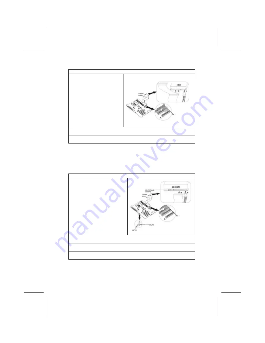
Installing a Hard Disk Drive 

1. 

Install the hard disk drive into the drive cage in your system case. 

2. 

Plug the IDE cable into IDE1 
(

A

): 

Note: 

 Ribbon cable connectors 

are usually keyed so that they can 
only be installed correctly on the 
device connector. If the connector 
is not keyed, make sure that you 
match the pin-1 side of the cable 
connector with the pin-1 side of the 
device connector. Each connector 
has the pin-1 side clearly marked. 
The pin-1 side of each ribbon ca-
ble is always marked with a 
colored stripe on the cable. 


3. 

Plug an IDE cable connector into the hard disk drive IDE connector (

B

). It 

doesn't matter which connector on the cable you use. 

4. 

Plug a power cable from the case power supply into the power connector on 
the hard disk drive (

C

). 

When you first start up your system, the BIOS should automatically detect 
your hard disk drive. If it d oesn’t, enter the Setup Utility and use the IDE Hard 
Disk Auto Detect feature to configure the hard disk drive that you have in-
stalled. 

Installing a CD-ROM/DVD Drive 

1. 

Install the CD-ROM/DVD drive into the drive cage in your system case. 

2. 

Plug the IDE cable into IDE1 
(

A

). If you have already installed 

an HDD, use the other connec-
tor on the IDE cable. 

Note: 

 Ribbon cable connectors are 

usually keyed so that they can only 
be installed correctly on the device 
connector. If the connector is not 
keyed, make sure that you match the 
pin-1 side of the cable connector with 
the pin-1 side of the device connec-
tor. Each connector has the pin-1 
side clearly marked. The pin-1 side of 
each ribbon cable is always marked 
with a colored stripe on the cable. 


3. 

Plug an IDE cable connector into the CD-ROM/DVD drive IDE connector (

B

). It 

doesn't matter which connector on the cable you use. 

4. 

Plug a power cable from the case power supply into the power connector on 
the CD-ROM/DVD drive (

C

). 

5. 

Use the audio cable provided with the CD-ROM/DVD drive to connect to the 
mainboard CD-in connector CDIN1 or CDIN2 (

D

). 

When you first start up your system, the BIOS should automatically detect 
your CD-ROM/DVD drive. If it doesn’t, enter the Setup Utility and configure 
the CD-ROM/DVD drive that you have installed.  

Summary of Contents for P4S5A

Page 1: ...tested and found to comply with the limits for a Class B digi tal device pursuant to Part 15 of the FCC Rules These limits are designed to provide reasonable protection against harmful interference in...

Page 2: ...erference causing Equipment Regulations Cet appareil num rique de la classe B respecte toutes les exigences du R glement sur le mat riel brouilieur du Canada About the Manual The manual consists of th...

Page 3: ...ing Jumpers 7 Checking Jumper Settings 8 Jumper Settings 8 Connecting Case Components 9 The FPI Connector 9 Installing Hardware 10 Installing the Processor 10 Installing Memory Modules 13 Installing a...

Page 4: ...Exit 35 CHAPTER 4 36 Using the Mainboard Software 36 About the Software CD ROM 36 Auto installing under Windows 98 36 Running Setup 37 Manual Installation 39 Utility Software Reference 39 Award Flash...

Page 5: ...udio Modem Riser slot to support Audio and Modem application and built in 10BaseT 100BaseTX Network Interface There is a full set of I O ports including two PS 2 ports for mouse and keyboard two seria...

Page 6: ...orts an AC 97 link for audio and modem hardware monitoring and ACPI OnNow power management Chipset This mainboard may support either one of the three Southbridge chipset Refer below for details SiS961...

Page 7: ...signaling and one EHCI Host Controller core for high speed signaling Supports PCI Bus Power Management Interface Specifi cation release 1 1 Legacy support for all downstream facing ports IEEE 1394 Con...

Page 8: ...pes of computer cases on the market The mainboard com plies with the specifications for the ATX system case Some features on the mainboard are implemented by cabling connectors on the mainboard to ind...

Page 9: ...5 M Ma ai in nb bo oa ar rd d C Co om mp po on ne en nt ts s...

Page 10: ...edges Do not bend circuit boards Q Qu ui ic ck k G Gu ui id de e This Quick Guide suggests the steps you can take to assemble your system with the mainboards The following table provides a reference...

Page 11: ...e appropriate 1 Place the mainboard over the mounting brackets Ensure that your case has an I O template that supports the I O ports and expansion slots on your mainboard C Ch he ec ck ki in ng g J Ju...

Page 12: ...4 1 JP3 4 pin Onboard LAN LED Jumper 1 2 Link LED 3 4 LED Active JP3 1 JP4 Clear CMOS Jumper Use this jumper to clear the contents of the CMOS memory You may need to clear the CMOS memory if the setti...

Page 13: ...ase you can begin connecting the mainboard components Refer to the following 1 Connect the power connector from the power supply to the ATX_PW1 connector on the mainboard 2 If there is a cooling fan i...

Page 14: ...ious damage to the mainboard or its components On most mainboards there are small surface mount resistors near the processor socket which may be damaged if the cooling fan is carelessly installed Avoi...

Page 15: ...nstallation Procedure The following illustration shows CPU installation components Note The pin 1 corner is marked with an arrow Follow these instructions to install the CPU 1 Install and secure the R...

Page 16: ...place Cooling Fan Retention Module Heatsink 9 Swing both lock levers on top of the cooling fan to their opposite sides to se cure the cooling fan on top of the heatsink 10 Connect the CPU Cooling Fan...

Page 17: ...sing and falling edges of the clock DDR SDRAM uses additional power and ground lines and requires 184 pin 2 5V unbuffered DIMM module rather than the 168 pin 3 3V unbuffered DIMMs used by SDRAM Instal...

Page 18: ...ble and you can add two more devices to the secondary IDE channel IDE devices have jumpers or switches that are used to set the IDE device as MASTER or SLAVE Refer to the IDE device user s manual When...

Page 19: ...at you have in stalled Installing a CD ROM DVD Drive 1 Install the CD ROM DVD drive into the drive cage in your system case 2 Plug the IDE cable into IDE1 A If you have already installed an HDD use th...

Page 20: ...ble connectors are usually keyed so that they can only be installed correctly on the device connector If the connector is not keyed make sure that you match the pin 1 side of the cable connector with...

Page 21: ...the 32 bit PCI interface AMR Slot The AMR Audio Modem Riser slot is an industry standard slot that allows for the installation of a special audio modem riser card Differ ent territories have differen...

Page 22: ...ll the edge connector of the add on card into the expansion slot Ensure that the edge con nector is correctly seated in the slot 3 Secure the metal bracket of the card to the system case with a screw...

Page 23: ...ut header This header allows the user to install auxiliary front oriented microphone and line out ports for easier access Pin Signal Name Pin Signal Name 1 3 5 7 9 MICIN MIC P 3 FPOUT R 5 NC FPOUT L 2...

Page 24: ...LAN signal auto matically resumes the system You must enable this item using the Power Management page of the Setup Utility Pin Signal Name 1 2 3 5VSB Ground SENSE If you have installed a modem use t...

Page 25: ...der to connect to any IEEE 1394 interface JP27 Pin Signal Name Pin Signal Name 1 3 5 7 VCC_BUS TPB 0 TPA 0 Shield 2 4 6 8 GND TPB 0 TPA 0 NC JP28 Pin Signal Name Pin Signal Name 1 3 5 7 VCC_BUS TPB 1...

Page 26: ...ional Use the LAN port to connect to the network USB Ports Use the USB ports to connect USB devices LPT1 Use LPT1 to connect printers or other parallel communications devices COM1 2 Use the COM ports...

Page 27: ...me Digital monitor flat panel White IEEE 1394 Grey Microphone Pink MIDI game Gold Parallel Burgundy PS 2 compatible keyboard Purple PS 2 compatible mouse Green Serial Teal or Turquoise Speaker out sub...

Page 28: ...ives diskette drives and peripherals Video display type and display options Password protection from unauthorized use Power management features The settings made in the Setup Utility affect how the co...

Page 29: ...vigation keys are listed below Key Function Esc Exits the current menu Scrolls through the items on a menu PU PD Modifies the selected field s values F10 Saves the current configuration and exits setu...

Page 30: ...Pri Slave Auto On Sec Master Auto On Sec Slave Auto On Floppy Drive A 1 44 MB 3 1 2 Floppy Drive B Not Installed Month Jan Dec ESC Exit Day 01 31 SelectItem Year 1901 2099 PU PD Modify Shift F2 Color...

Page 31: ...C Quit SelectItem F1 Help PU PD Modify F5 Old Values Shift F2 Color F6 Load BIOS Defaults F7 Load Setup Defaults Quick Boot If you enable this item the system starts up more quickly be elimination som...

Page 32: ...ster execution Graphic Win Size This item defines the size of aperture if you use a graphic adapter DRAM CAS Latency This item determines the operation of DRAM memory CAS column address strobe It is r...

Page 33: ...nt scheme Both APM and ACPI are supported Suspend Time Out This sets the timeout for Suspend mode in minutes If the time selected passes without any system activity the computer will enter power savin...

Page 34: ...re O S Yes Primary Graphics Adapter PCI Allocate IRQ for PCI VGA Yes ESC Quit SelectItem F1 Help PU PD Modify F5 Old Values Shift F2 Color F6 Load BIOS Defaults F7 Load Setup Defaults Plug and Play Aw...

Page 35: ...onnected to the system AMIBIOS SETUP FEATURES SETUP C 2000 American Megatrends Inc All Rights Reserved OnBoard FDC Enabled OnBoard Serial PortA 3F8h COM1 OnBoard Serial PortB 2F8h COM2 Serial Port2 Mo...

Page 36: ...e this item to enable or disable the onboard Game port OnBoard MIDI Port Use this item to enable or disable the onboard MIDI port and to assign a port address MIDI Port IRQ Use this item to assign an...

Page 37: ...hts Reserved CPU Type Intel P4 CPU DRAM Speed 100 100 MHz CPU Core Voltage 1 616V CPU Ratio H W Trap CPU Frequency 100 MHz DRAM Frequency 100 MHz ESC Quit SelectItem F1 Help PU PD Modify F5 Old Values...

Page 38: ...SB3V 3 264V 12V 0 907V SB5V 5 053V VBAT 3 488V SYSTEM Fan Speed 0 RPM CPU Fan Speed 5400 RPM Power Temperature 33 C 91 F SYSTEM Temperature 40 C 104 F CPU Temperature 35 C 95 F ESC Quit SelectItem F1...

Page 39: ...en required to access the Setup Utility or for that and at start up depending on the setting of the Password Check item in Advanced Setup Change or Remove the Password Highlight this item press Enter...

Page 40: ...ADME TXT INSTALL TXT or something similar These files may contain important information that is not included in this manual A Au ut to o i in ns st ta al ll li in ng g u un nd de er r W Wi in nd do ow...

Page 41: ...ly Some software is installed in separate folders for different oper ating systems such as DOS WIN NT or WIN98 95 Always go to the correct folder for the kind of OS you are using To install the softwa...

Page 42: ...k Next The following screen appears Check the items you want to install The default options are recommended Click Next to run the Installation Wizard An item installation screen appears Follow the ins...

Page 43: ...nvenience of customers The following software is furnished under license and may only be used or copied in accordance with the terms of the license Note The software in these folders is subject to cha...

Page 44: ...binet of CD ROM drives on your system to help you categorize and organize your CD collection A user friendly interface assists you in quickly creating images of both CDs and DVDs onto your system To i...

Reviews: