ECS P4IBAD2 Manual Download Page 31


27 

2. 

If your mainboard has an item called Firmware Write Protect in Advanced 
BIOS features, disable it. (Firmware Write Protect prevents BIOS from being 
overwritten.)  

3. 

Create a bootable system disk. (Refer to Windows online help for info r-
mation on creating a bootable system disk.) 

4. 

Download the Flash Utility and new BIOS file from the manufacturer's 
Web site. Copy these files to the system diskette you created in Step 3. 

5. 

Turn off your computer and insert the system diskette in your computer's 
diskette drive. (You might need to run the Setup Utility and change the boot 
priority items on the Advanced BIOS Features Setup page, to force your 
computer to boot from the floppy diskette drive first.) 
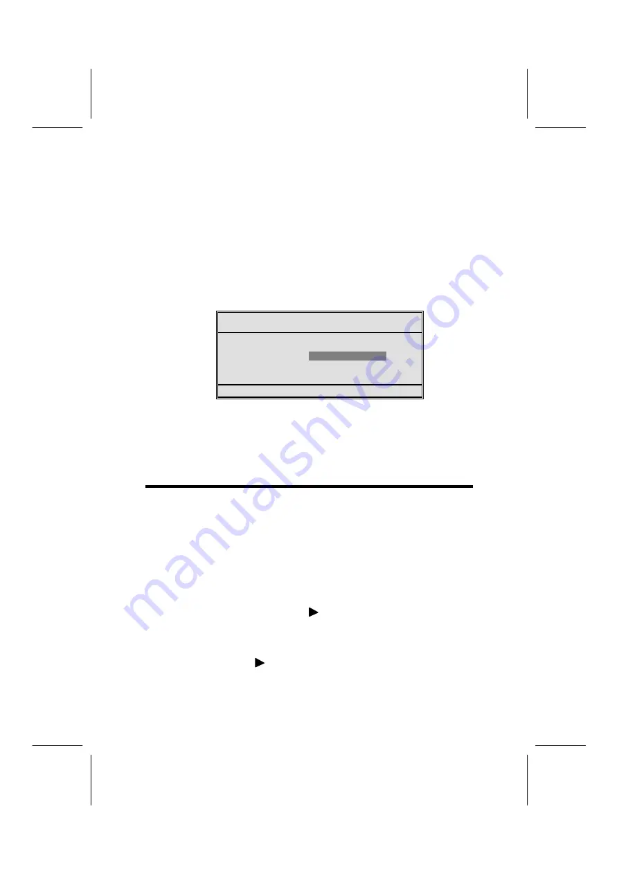
6. 

At the A:\ prompt, type the Flash Utility program name and press <En-
ter>. You see a screen similar to the following: 

FLASH MEMORY WRITER V7.33 

(C) Award Software 1999 All Rights Reserved 

For (MAINBOA RD NAME) 

DATE: 10/26/2000 

Flash Type 
File Name to Program :____________________ 


Error Message 

7. 

Type the filename of the new BIOS in the “File Name to Program” text 
box. Follow the onscreen directions to update the mainboard BIOS. 

8. 

When the installation is complete, remove the floppy diskette from the 
diskette drive and restart your computer. If your mainboard has a Flash 
BIOS jumper, reset the jumper to protect the newly installed BIOS from 
being overwritten. 

U

U

s

s

i

i

n

n

g

g


B

B

I

I

O

O

S

S


When you start the Setup Utility, the main menu appears. The main menu of 
the Setup Utility displays a list of the options that are available. A highlight 
indicates which option is currently selected. Use the cursor arrow keys to 
move the highlight to other options. When an option is highlighted, execute 
the option by pressing <Enter>.  

Some options lead to pop-up dialog boxes that prompt you to verify that you 
wish to execute that option. Other options lead to dialog boxes that prompt 
you for information.  

Some options (marked with a triangle 

) lead to submenus that enable you 

to change the values for the option. Use the cursor arrow keys to scroll 
through the items in the submenu.   

In this manual, default values are enclosed in parenthesis. Submenu items 
are denoted by a triangle 


Summary of Contents for P4IBAD2

Page 1: ...ested and found to comply with the limits for a Class B digi tal device pursuant to Part 15 of the FCC Rules These limits are designed to provide reasonable protection against harmful interference in...

Page 2: ...erference causing Equipment Regulations Cet appareil num rique de la classe B respecte toutes les exigences du R glement sur le mat riel brouilieur du Canada About the Manual The manual consists of th...

Page 3: ...ng Jumpers 8 Checking Jumper Settings 9 Jumper Settings 9 Connecting Case Components 10 Front Panel Connector 12 Installing Hardware 13 Installing the Processor 13 Installing Memory Modules 16 Install...

Page 4: ...ontrol 42 Load Fail Safe Defaults Option 43 Load Optimized Defaults Option 43 Set Supervisor User Password 43 Save Exit Setup Option 44 Exit Without Saving 44 CHAPTER 4 45 Using the Mainboard Software...

Page 5: ...eatures conveniently integrated on the rear I O panel includingsupport for PS 2 keyboard and mouse connectors two USB ports a LAN connector two high speed serial port an EPP ECP parallel port audio ja...

Page 6: ...p to six channels Additional key features include support for an AC 97 link for audio and modem hardware monitoring and ACPI OnNow power man agement Memory Supports DDR up to 200 266 333 enhanced MHz...

Page 7: ...x 32 bit PCI slots One 4xAGP slot support 1 5V only One Communications Network Riser CNR slot Two IDE connectors which support four IDE channels and a floppy disk drive interface The P4IBAD2 supports...

Page 8: ...e Ensure that your case supports all the features required The mainboard can support one or two floppy diskette drives and four enhanced IDE drives Ensure that your case has sufficient power and space...

Page 9: ...5 M Ma ai in nb bo oa ar rd d C Co om mp po on ne en nt ts s...

Page 10: ...ser slot CPU Socket CPU socket mPGA478 DIMM1 DIMM2 Two 184 pin DDR sockets FDD1 Floppy disk drive connector IDE 1 Primary IDE channel IDE 2 Secondary IDE channel JP1 Clear CMOS jumper JP2 BIOS protect...

Page 11: ...he edges Do not bend circuit boards Q Qu ui ic ck k G Gu ui id de e This Quick Guide suggests the steps you can take to assemble your system with the mainboards The following table provides a referenc...

Page 12: ...e appropriate 1 Place the mainboard over the mounting brackets Ensure that your case has an I O template that supports the I O ports and expansion slots on your mainboard C Ch he ec ck ki in ng g J Ju...

Page 13: ...sh protection Short Flash protect Open Flash JP2 JP4 3 pin Disable USB function 1 2 Enabled 2 3 Disabled JP4 1 JP1 Use this jumper to clear the contents of the CMOS memory You may need to clear the CM...

Page 14: ...e mainboard into a case you can begin connecting the mainboard components Refer to the following 1 Connect the case power supply connector to ATX1 2 Connect the CPU cooling fan cable to CPUFAN1 3 Conn...

Page 15: ...5V 9 5VSB 19 5V 10 12V 20 5V SJI Single color LED header Pin Signal Name 1 ACPI LED 2 ACPI LED 3 5VSB ACPI LED function S0 S1 S3 S4 S5 SJ1 1 Light Blinking Blinking Dark LSJI Single color LED header f...

Page 16: ...itten to the hard drive For the LED to function properly an IDE drive should be connected to the onboard IDE inter face The LED will also show activity for devices connected to the SCSI hard drive act...

Page 17: ...installing the Processor This mainboard automatically determines the CPU clock frequency and sys tem bus frequency for the processor You may be able to change these settings by making changes to jump...

Page 18: ...e instructions to install the Retention Module and CPU 1 Remove the existing retention module if applicable 2 Position the backplate against the underside of the mainboard secure the 4 screws firmly o...

Page 19: ...wn on the retention module and snap the four reten tion legs of the cooling fan into place 8 Flip the levers over to lock the heat sink in place 9 Connect the CPU Cool ing Fan power cable to the CPUFA...

Page 20: ...you are ready to install it on the mainboard Handle the modules only by their edges Do not touch the components or metal parts Always wear a grounding strap when you handle the modules Installation Pr...

Page 21: ...l IDE devices that support UDMA and use 80 pin IDE ca bles that support UDMA 66 100 Installing a Hard Disk Drive 1 Install the hard disk drive into the drive cage in your system case 2 Plug the IDE ca...

Page 22: ...If it doesn t enter the Setup Utility and configure the CD ROM DVD drive that you have installed See IDE Primary Secondary Master Slave Auto on page 29 for more information Installing a Floppy Disket...

Page 23: ...VT6202 USB 2 0 is present on the mainboard the PCI 6 will be automatically set to Slave PCI 4xAGP Slot The 4xAGP slot is used to install a graphics adapter that supports the 4xAGP specification and ha...

Page 24: ...the edge connector of the add on card into the expansion slot Ensure that the edge con nector is correctly seated in the slot 3 Secure the metal bracket of the card to the system case with a screw Not...

Page 25: ...D_MIC Front Panel Microphone input signal 2 AUD_GND Ground used by Analog Audio Circuits 3 AUD_MIC_BIAS Microphone Power 4 AUD_VCC Filtered 5 V used by Analog Audio Circuits 5 AUD_FPOUT_R Right Channe...

Page 26: ...ort 0 Positive Signal 6 USB_FP_P1 USB Port 1 Positive Signal 7 GND Ground 8 GND Ground 9 KEY No pin 10 USB_FP_OC0 Overcurrent signal Note Please make sure that the USB cable has the same pin assignmen...

Page 27: ...ports to connect USB devices LPT1 Use LPT1 to connect printers or other parallel communica tions devices COM1 2 Use the COM ports to connect serial devices such as mice or fax modems COM1 is identifie...

Page 28: ...ne out Lime Digital monitor flat panel White IEEE 1394 Grey Microphone Pink MIDI game Gold Parallel Burgundy PS 2 compatible keyboard Purple PS 2 compatible mouse Green Serial Teal or Turquoise Speake...

Page 29: ...rives diskette drives and peripherals Video display type and display options Password protection from unauthorized use Power management features The settings made in the Setup Utility affect how the c...

Page 30: ...ithout Saving Esc Quit Select Item F10 Save Exit Setup Time Date Hard Disk Type BIOS Navigation Keys The BIOS navigation keys are listed below Key Function Esc Exits the current menu Scrolls through t...

Page 31: ...ge 7 Type the filename of the new BIOS in the File Name to Program text box Follow the onscreen directions to update the mainboard BIOS 8 When the installation is complete remove the floppy diskette f...

Page 32: ...ime items show the current date and time on the computer If you are running a Windows OS these items are automatically updated when ever you make changes to the Windows Date and Time Properties utilit...

Page 33: ...an result in your system not recognizing the installed hard disk Access Mode This item defines ways that can be used to access IDE hard disks such as LBA Large Block Addressing Leave this value at Aut...

Page 34: ...ors that can be installed in this mainboard use internal level 1 L1 and external level 2 L2 cache memory to improve performance Leave this item at the default value for better performance Quick Power...

Page 35: ...nly required when a user tries to enter the Setup Utility APIC Mode Enable This option enables disables APIC Advanced Programmable Interrupt Con troller functionality The APIC is an Intel chip that pr...

Page 36: ...6 Min Menu Level Move Enter Select PU PD Value F10 Save ESC Exit F1 General Help F5 Previous Values F6 Fail Safe Defaults F7 Optimized Defaults DRAM Timing Selectable Manual The value in this field de...

Page 37: ...BIOS and RAM to be cached in memory for faster execution Enable these items for better performance Memory Hole At 15M 16M Disabled You can reserve this area of system memory for ISA adapter ROM When t...

Page 38: ...Use these items to enable or disable the PCI IDE channels that are integrated on the mainboard IDE Primary Secondary Master Slave PIO Auto Each IDE channel supports a master device and a slave device...

Page 39: ...parameters The default setting enables you to use a hot key to turn on the system KB Power ON Password Enter When the POWER ON Function is set to Password use this item to set the password Hot Key Po...

Page 40: ...board parallel port Parallel Port Mode ECP Enables you to set the data transfer protocol for your parallel port There are four options SPP Standard Parallel P ort EPP Enhanced Parallel Port ECP Extend...

Page 41: ...led ACPI Suspend Type S1 POS Power Management User Define Video Off Method DPMS Video Off In Suspend Yes Suspend Type Stop Grant MODEM Use IRQ 3 Suspend Mode Disable HDD Power Down Disable Soft Off by...

Page 42: ...saving mode use this item to specify the interrupt request line IRQ that is used by the modem You might have to connect the fax modem to the mainboard Wake On Modem connector for this feature to work...

Page 43: ...events are I O events whose occurrence can prevent the system from entering a power saving mode or can awaken the system from such a mode In effect the system remains alert for anything that occurs to...

Page 44: ...annot boot Move Enter Select PU PD Value F10 Save ESC Exit F1 General Help F5 Previous Values F6 Fail Safe Defaults F7 Optimized Defaults Reset Configuration Data Disabled If you enable this item and...

Page 45: ...Shutdown Temperature Disabled CPU Vcore 1 80 V 3 30 V 5 00 V 12 0 V Voltage Battery Current System Temp Current CPU Temp CPU FAN Speed Chassis FAN Speed Power FAN Speed Chassis has been Close Chassis...

Page 46: ...U PD Value F10 Save ESC Exit F1 General Help F5 Previous Values F6 Fail Safe Defaults F7 Optimized Defaults CPU Clock Ratio Enables you to set the CPU clock The CPU clock ratio times the CPU Host PCI...

Page 47: ...specific option select and display that option and then press F7 Set Supervisor User Password When this function is selected the following message appears at the center of the screen to assist you in...

Page 48: ...item and press Enter to discard any changes that you have made in the Setup Utility and exit the Setup Utility When the Exit Without Sav ing dialog box appears press Y to discard changes and exit or...

Page 49: ...r something similar These files may contain important information that is not included in this manual A Au ut to o i in ns st ta al ll li in ng g u un nd de er r W Wi in nd do ow ws s 9 98 8 M ME E 2...

Page 50: ...ly Some software is installed in separate folders for different oper ating systems such as DOS WIN NT or WIN98 95 Always go to the correct folder for the kind of OS you are using To install the softwa...

Page 51: ...ing screen appears 3 Check the box next to the items you want to install The default options are recommended 4 Click Next run the Installation Wizard An item installation screen ap pears 5 Follow the...

Page 52: ...copied in accordance with the terms of the license Note These software s are subject to change at anytime without prior notice Please refer to the support CD for available software AWARD Flash Memory...

Page 53: ...quickly creating images of both CDs and DVDs onto your system To install the software run SETUP EXE from the following directory UTILITY CDGHOST ENG CDGHOST Recovery Genius The Recovery Genius softwa...

Reviews: