ECS MCP61M-M3 Manual Download Page 19

15

Installing the Motherboard

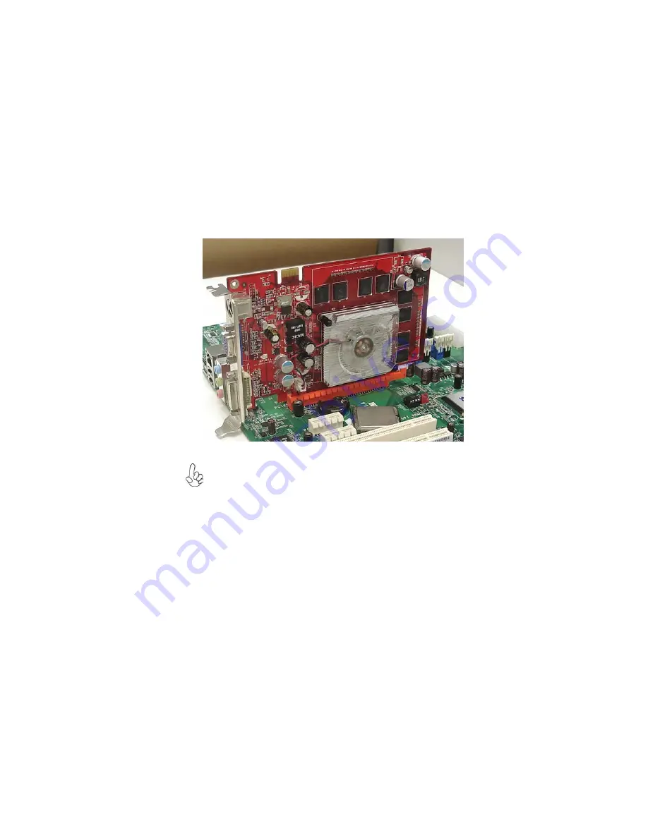
Follow these instructions to install an add-on card:

1

Remove a blanking plate from the system case corresponding to the

slot you are going to use.

2

Install the edge connector of the add-on card into the expansion slot.

Ensure that the edge connector is correctly seated in the slot.

3

Secure the metal bracket of the card to the system case with a screw.

For some add-on cards, for example graphics adapters and network adapt-
ers, you have to install drivers and software before you can begin using the
add-on card.

Summary of Contents for MCP61M-M3

Page 1: ...quency energy and if not installed and used in accordance with the instructions may cause harmful inter ference to radio communications However there is no guarantee that interference will not occur i...

Page 2: ...sur le mat riel brouilieur du Canada AbouttheManual The manual consists of the following Chapter 1 Introducing the Motherboard Chapter 2 Installing the Motherboard Chapter 3 Using BIOS Chapter 4 Using...

Page 3: ...Checking Jumper Settings 9 Jumper Settings 9 InstallingHardware 10 Installing the Processor 10 Installing Memory Modules 12 Expansion Slots 14 Connecting Optional Devices 16 Installing a Hard Disk Dri...

Page 4: ...underWindows XP Vista 7 45 Running Setup 46 ManualInstallation 48 UtilitySoftwareReference 48 Chapter 5 49 49 49 49 49 SettingUpNVIDIARAIDConfiguration 49 Setting Up a Non Bootable RAIDArray 49 Settin...

Page 5: ...ler The memory controller supports DDR3 memory DIMM frequencies of 1333 1066 800 It supports two DDR3 sockets with maximum memory size of 8 GB High resolution graphics via one PCI Express x16 slot one...

Page 6: ...port 44 1 48k 96k 192k sample rate Power Support Digital 3 3V Analog 5 0V The onboard Audio provides the following features The NVIDIA MCP61P is a single chip with proven reliability and performance 1...

Page 7: ...d One serial port One optional parallel port One VGA port Four USB ports One LAN port Audio jacks for microphone line in and line out BIOS Firmware Power management Wake up alarms CPU parameters CPU a...

Page 8: ...4 IntroducingtheMotherboard Motherboard Components...

Page 9: ...power connector 7 IDE Primary IDE connector 8 SATA1 4 Serial ATA connectors 9 PANEL Front panel Switch LED header 10 F_USB1 3 Front panel USB headers 11 USBPWR_F Front panel USB power select jumper 1...

Page 10: ...6 IntroducingtheMotherboard Memo...

Page 11: ...that your case supports all the features required Secondly this motherboard supports one floppy diskette drive and two enhanced IDE drives Make sure that your case has sufficient power and space for a...

Page 12: ...han one pin are numbered When setting the jumpers ensure that the jumper caps are placed on the correct pins The illustrations show a 2 pin jumper When the jumper cap is placed on both pins the jumper...

Page 13: ...ides enough VCC5_DUAL voltage before selecting the VCC5_DUAL function 3 It is required that users place the USBPWR_F USBPWR_R cap onto 2 3 pin rather than 1 2 pin as default if you want to wake up the...

Page 14: ...or You may be able to change these settings by making changes to jumpers on the motherboard or changing the settings in the system Setup Utility We strongly recommend that you do not over clock proces...

Page 15: ...y 1 Unhook the locking lever of the CPU socket Pull the locking lever away from the socket and raising it to the upright position 2 Match the pin1 corner marked as the beveled edge on the CPU with the...

Page 16: ...until it seats correctly The slot latches are levered upwards and latch on to the edges of the DIMM 6 Install any remaining DIMM modules Installing Memory Modules This motherboard accommodates two 24...

Page 17: ...sung Golden Bar M378B2873DZ1 CF8 0818 HYMT125U64ZNF8 G8 AA Hynix HMT125U6AFP8C G7N0 AA MT16JTF25664AY 1G1D1 Micron MT16JTF25664AY 1G1D1 IMSH2GU13A1F1C 10F B3S81427044 Qimonda IMSH2GU13A1F1C 10G B3S815...

Page 18: ...xternal PCI Express graphics card that is fully compliant to the PCI Express Base Speci fication revision 1 1 PCI1 2 Slots This motherboard is equipped with two standard PCI slots PCI stands for Perip...

Page 19: ...use 2 Install the edge connector of the add on card into the expansion slot Ensure that the edge connector is correctly seated in the slot 3 Secure the metal bracket of the card to the system case wi...

Page 20: ...PORT1R 4 PRESENCE 5 PORT2R 6 SENSE1_RETURN 7 SENSE_SEND 8 KEY Pin Signal Name 9 PORT2L 10 SENSE2_RETURN Pin Signal Name SATA1 4 Serial ATA connectors These connectors are used to support the new Seria...

Page 21: ...liary USB connector to connect the front mounted ports to the motherboard Please make sure that the USB cable has the same pin assignment as indicated above A different pin assignment may cause damage...

Page 22: ...allow the wire less exchange of information between your computer and similarly equipped devices such as printers laptops Personal Digital Assistants PDAs and other computers 1 Not Assigned Not assign...

Page 23: ...Technology Attachment is the standard inter face for the IDE hard drives which are currently used in most PCs These connectors are well designed and will only fit in one orientation Locate the SATA c...

Page 24: ...ch the SATA power cable to the SATA hard drive and connect the other end to the power supply Installing a Floppy Diskette Drive You must orient the cable connector so that the pin 1 color edge of the...

Page 25: ...t serial devices such as mice or COM fax modems LAN Port Connect an RJ 45 jack to the LAN port to connect your computer to the Network USB Ports Use the USB ports to connect USB devices Use the three...

Page 26: ...Connect the standard power supply connector to PWR 4 Connect the auxiliary case power supply connector to ATX_12V 5 Connect the case switches and indicator LEDs to the PANEL 6 Connec the case speaker...

Page 27: ...5VSB 21 5V 10 12V 22 5V 11 12V 23 5V 12 3 3V 24 Ground SYS_FAN System Cooling FAN Power Connector Pin Signal Name Function 1 GND System Ground 2 12V Power 12V 3 Sense Sensor CPU_FAN FAN Power Connecto...

Page 28: ...connected to the onboard IDE interface The LED will also show activity for devices connected to the SCSI hard drive activity LED connector Pin Signal Function Pin Signal Function 1 HD_LED_P HarddiskLE...

Page 29: ...ures The settings made in the Setup Utility affect how the computer performs Before using the Setup Utility ensure that you understand the Setup Utility options This chapter provides explanations for...

Page 30: ...ST screen may show a CMOS Settings Wrong message This standard message will appear following a clear CMOS data at factory by the manufacturer You simply need to Load Default Settings to reset the defa...

Page 31: ...change the values for the option Use the cursor arrow keys to scroll through the items in the submenu In this manual default values are enclosed in parenthesis Submenu items are denoted by a triangle...

Page 32: ...Detected SATA2 Not Detected SATA3 Not Detected SATA4 Not Detected IDE BusMaster Enabled Drive A 1 44MB31 2 Help Item f f CMOS Setup Utility Copyright C 1985 2005 American Megatrends Inc Time 00 12 01...

Page 33: ...The S M A R T Self Monitoring Analysis and Reporting Technology system is a diagnostics technology that monitors and predicts device performance S M A R T software resides on both the disk drive and t...

Page 34: ...he DMA under DOS mode We recommend you to leave this item at the default value Drive A 1 44 MB 31 2 This item defines the characteristics of any diskette drive attached to the system You can connect o...

Page 35: ...isplay and the options are 200 MHz 400 MHz 600 MHz 800 MHz and 1000 MHz Quick Power on Self Test Enabled Enable this item to shorten the power on testing POST and have your system start up faster You...

Page 36: ...LOPPY DRIVE Help Item Specifies the boot sequence from the availabledevices F10 Save ESC Exit Value Enter Select F9 Optimized Defaults F1 General Help Move mnlk CMOS Setup Utility Copyright C 1985 200...

Page 37: ...d be set to 32 MB CMOS Setup Utility Copyright C 1985 2005 American Megatrends Inc Advanced Chipset Setup Dram Frequency Auto Dram Timing Auto DCT Unganged Mode Always Share Memory Auto Detection Auto...

Page 38: ...Enabled Onboard LAN Function Enabled Onboard LAN Boot ROM Disabled Serial Port1 Address 3F8 IRQ4 OnBoard IR Disabled USB Functions Enabled Legacy USB Support Enabled f DISABLED disables the integrated...

Page 39: ...tem to enable or disable the booting from the onboard LAN or a network add in card with a remote boot ROM installed Serial Port1 Address 3F8 IRQ4 Use this item to enable or disable the onboard COM1 se...

Page 40: ...d mode is a suspend to RAM i e the system shuts down with the exception of a refresh current to the system memory Resume By Ring Disabled An input signal on the serial Ring Indicator RI line in other...

Page 41: ...e system can automatically resume at a fixed time based on the system s RTC realtime clock Use the items below this one to set the date and time of the wake up alarm You must use an ATX power supply i...

Page 42: ...s F1 General Help Move mnlk PC Health Status On motherboards support hardware monitoring this item lets you monitor the parameters for critical voltages temperatures and fan speeds CMOS Setup Utility...

Page 43: ...fan speed will be auto restricted to make system more quietly If you choose Manual mode the fan speed will be adjust depending on users parameters CMOS Setup Utility Copyright C 1985 2005 American Meg...

Page 44: ...lue Enter Select F9 Optimized Defaults F1 General Help Move mnlk Press Esc to return to the PC Health Status page FAN1 Mode Setting Enabled SMART Fan Mode Manual High Limit Temperature C 68 Low Limit...

Page 45: ...ltage Control Help Item Options Disabled Enabled F10 Save ESC Exit Value Enter Select F9 Optimized Defaults F1 General Help Move mnlk Auto Detect DIMM PCI CIK Enabled SpreadSpectrum Enabled Auto Detec...

Page 46: ...rvisor Password This page helps you install or change a password CMOS Setup Utility Copyright C 1985 2005 American Megatrends Inc Supervisor Password Install or Change the password Help Item Superviso...

Page 47: ...ther a user password has been set If the password has been installed Installed displays If not Not Installed displays Change User Password Press Enter You can select this option and press Enter to acc...

Page 48: ...tem disk Refer to Windows online help for information on creating a bootable system disk 4 Download the Flash Utility and new BIOS file from the manufacturer s Web site Copy these files to the bootabl...

Page 49: ...o installation optional The Intel High Defi nition audio functionality unexpectedly quits working in Windows Server 2003 Service Pack 1 or Windows XP Professional x64 Edition Users need to download an...

Page 50: ...driver lists will be different according to the motherboard you are installing The motherboard identification is located in the upper left hand corner The Browse CD button is the standard Windows com...

Page 51: ...ns are recom 4 Click Next run the Installation Wizard An item installation screen appears 5 Follow the instructions on the screen to install the items mended Drivers and software are automatically ins...

Page 52: ...nd locate the readme text file README TXT or README DOC for information on installing the driver or software for your oper ating system Utility Software Reference All the utility software available fr...

Page 53: ...nfiguration one is to create a RAID 1 Array for backup or a RAID 0 Array for increased performance just by adding additional disk array without changing the original OS Non Bootable RAID Array while t...

Page 54: ...the NVIDIA Windows nForce Drivers page Figure 1 3 nForce Driver Installation Window 3 4 1 save the current configuration and exit setup in BIOS setting The PC reboots Make sure that the NVIDIA IDE Dr...

Page 55: ...s see Figure 1 4 then press Enter The Integrated Peripherals screen or a screen similar to it appears Figure 1 5 Integrated Peripherals Screen From the Integrated Peripherals Window globally set SATA...

Page 56: ...ID BIOS The NVIDIA RAID BIOS set up lets you choose the RAID type and which hard drives you want to make part of the array EnteringtheRAIDBIOSSetup 1 Wait until you see the RAID software prompting you...

Page 57: ...block These are the drives that are available for use as RAID array disks To designate a free disk to be used as a RAID array disk By default this is set to Mirroring To change to a different RAID mo...

Page 58: ...Array screen after one disk have been assigned as RAID 0 array disk Figure 1 8 MediaShield BIOS Array Disks Assigned Completing the RAID BIOS Setup Figure 1 9 Clear Disk Data Prompt After assigning y...

Page 59: ...iping Block used RAID Mode Striping Width Disk Model Name and disk capacity If you want to mark this disk as empty and wipe out all its contents press C At the prompt press Y to wipe out all the data...

Page 60: ...t If that is not the case or you are trying to install a new version of Windows then you will need an NVIDIA RAID driver F6 install floppy Check to see if one came with your system If not you can crea...

Page 61: ...ion Be sure to leave the floppy disk inserted in the floppy drive until the blue screen portion of Windows XP installation is completed then take out the floppy Follow the instructions on how to insta...

Page 62: ...58 NVIDIARAIDConfiguration Memo...

Page 63: ...t enjoyment on web browsing photo review and online chat just within several seconds after boot up Version 5 0 Note eJIFFY is ECS optional feature utility corresponding to the DVD activation and BIOS...

Page 64: ...ctivation Finish the DVD utility setup and then set the BIOS to complete eJIFFY activation 1 Insert ECS software utility DVD and enter below Utilities screen Click eJIFFY feature item to install 2 Fol...

Page 65: ...display keyboard language from English to your local language The changes will be applied after rebooting Note The keyboard language selection list offers several more regional keyboard setups to swi...

Page 66: ...ge after boot up 5 And then enter the Advanced Setup page to enable the item ECS eJIFFY Func tion Press F10 to save the configuration and exit Restart your computer 2 Please refer to ECS website for n...

Page 67: ...hree buttons on it Operating system eJIFFY and BIOS Setup If you click eJIFFY the following screen will appear And If you make no choice it will enter the normal OS automatically after ten seconds Cli...

Page 68: ...Shut Down Restart Ends your session and turns off the computer Ends your session and restart the computer Click once to connect the storage disk to your computer Click for the second time to remove y...

Page 69: ...multi language displays and keyboard settings for language switch Open the language control panel to select a preferable language setting Step1 Click Step 2 Click Keyboard Language icon to open the k...

Page 70: ...uage bar here Move your mouse pointer on the text box and press Ctrl Space The language bar will then appear as fol lows Select your desired language Click to enable all possible language inputs you w...

Page 71: ...nguage Open the Language Control Panel and click to show the display language list Check your desired display language Your selected display language will be applied after rebooting Details about eJIF...

Page 72: ...SettingUpeJIFFY 68 Memo...

Page 73: ...rivers from the inside PC case This is to prevent damage from short circuit 3 Check the CPU FAN connector is connected to the motherboard 4 For Intel platforms check the pins on the CPU socket for dam...

Page 74: ...ptimised Default in the BIOS setup 2 Check the CPU cooler fan for dust Long term accumulation of dust will reduce its effectiveness to cool the processor Clean the cooler or replace a new one if neces...

Page 75: ...ct RMA No If 3 short beeps DIMM memory not properly inserted or memory failure If 1 long beep and 8 short beeps VGA not detected Yes Yes Halt at POST screen Yes R CMO L C S and restart If fail contact...

Page 76: ...72 TroubleShooting Memo...

Reviews: