2
© ECS Electronics B.V.
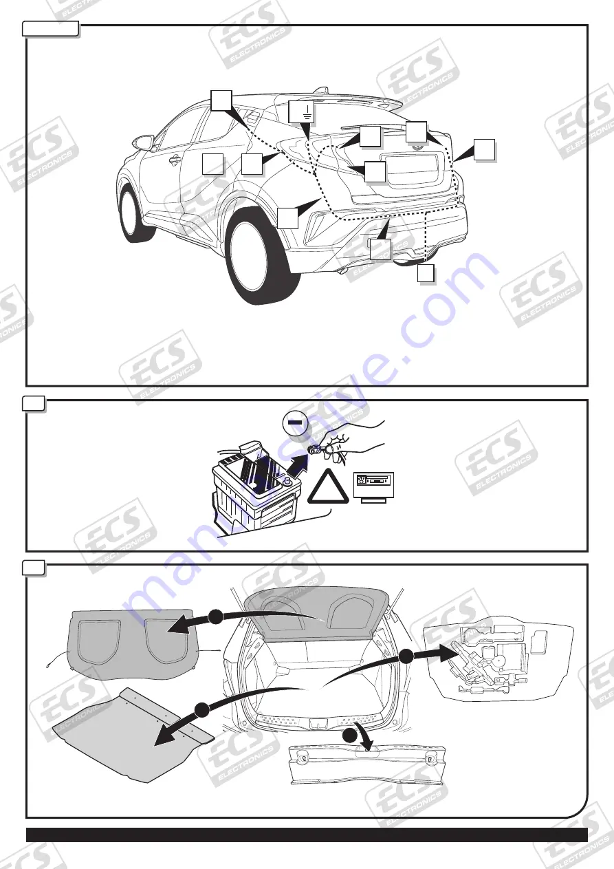
Pag. 3 TO-245-HHU / 190417CD
!
Code
3:3
ROUTING
1
R2
R1
L1
L2
L3
B
M
+
X
A
G
C
4
3
Page 1: ...f these kits and their fitting manuals are subject to alteration without notice please ensure that these instructions are read and fully understood before commencing installation Do not overload circu...
Page 2: ...sanleitung Mode d emploi Gebruikershandleiding User guide Gu a del usuario Manuale di istruzioni Bruksanvisning ECS Electronics B V www ecs electronics com CT 026 DL 210305RH Revision 0 Citro n C4 Hat...
Page 3: ...2 ECS Electronics B V Pag 3 TO 245 HHU 190417CD Code 3 3 ROUTING 1 R2 R1 L1 L2 L3 B M X A G C 4 2 1 3...
Page 4: ...ECS Electronics B V Pag 4 TO 245 HHU 190417CD 3 4 1 2 10mm 3 5 4...
Page 5: ...ECS Electronics B V Pag 5 TO 245 HHU 190417CD 5 C X R2 L3 1 2 X SEAL WITH SILICONE 3 A B Option 1 X Pag 12 SOCKET CONNECTION Option 1 Option 2...
Page 6: ...ECS Electronics B V Pag 6 TO 245 HHU 190417CD 7 6 E F Option 2 Option 3 2 3 4 1 2 3 4 1 D DISCONNECT 4 3 1 2 10mm...
Page 7: ...DISCONNECT 4 3 10mm 2 1 ECS Electronics B V Pag 7 TO 245 HHU 190417CD 9 7 8 R1 R1 R2 1 2 3 2 1 3 4 SEAL WITH SILICONE 1 2 3...
Page 8: ...SEAL WITH SILICONE ECS Electronics B V Pag 8 TO 245 HHU 190417CD 10 11 L1 L1 2 3 1 L2 2 1 3 4 1 2 3...
Page 9: ...ECS Electronics B V Pag 9 TO 245 HHU 190417CD 12 Remove tape Brown White 1 6 7 4 3 5 8 L3 9 Brown White Red Yellow Grey 2...
Page 10: ...ECS Electronics B V Pag 10 TO 245 HHU 190417CD 14 15 16 A 2 1 3 10 mm G 1 2 13 1 2 3 B M C M B B 1 2 3 4 1x 2x M M 5 6 7 2x...
Page 11: ...CS Electronics B V Pag 11 TO 245 HHU 190417CD 2 Reverse 1 2 C Red 2 3 Green Red 1 3 Red 4 19 17 18 M FOR CONVENTIONAL FOR HYBRID 1x 20 Amp 2 0 A m p TOWING B 1x 20 Amp 2 0 A m p TOWING B B Remove tape...
Page 12: ...RIM DU FR NL GB ES IT SE CZ DK FI GR NO PL Bedienungsanleitung Mode d emploi Gebruikershandleiding User guide Gu a del usuario Manuale di istruzioni Bedienungsanleitung Mode d emploi Gebruikershandlei...
Page 13: ...he cut wire is connected and the system operates normally When the trailer is connected This wire becomes disconnected by the Trailer Module If the same module also controls the Front Sensors then use...
Page 14: ...OPTION 1 NO PDC MUTE PDC UNIT PDC MUTE 12 Volt 12 Volt Reverse signal D C E B G F A P D C PDC Manual OPTIONS A B OPTIONS F G C D E 1 M 2 3 9 7 9 7 9 7 5 12 Volt 1 2 4 5 3 PDC MUTE AFTER MARKET NON OE...