47
A
B
C
Fault Finding Solutions Sections
1.
2.
3.
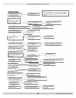
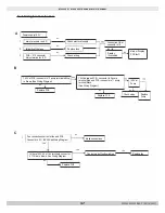
Power supply 120V
1.
NO
Main terminals L and N
Check electrical supply
Connection OK at
connector x1 0
NO
Integrity of the fuse
Replace fuse
YES
NO
PCB - X1 0 connector
Check wiring
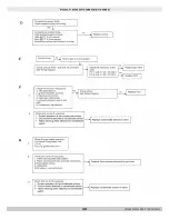
Display
illuminated
Mains terminals L & N
120V at PCB -connector x13 pump terminals Blue
to Brown (See Wiring Diagram)
NO
Replace PCB
Fan connections correct at fan and PCB
Connectors X11 & X23 See Wiring Diagram
YES
NO
120V between PCB -connector x13 pump
terminal Blue and PCB -connector x11 pump
terminal Black.
(See Wiring Diagram)
NO
Replace PCB
Make connections
Main or Display
PCB fault
120V at
Pump
NO
Check wiring
Replace
Pump
YES
YES
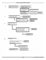
Is there 120V AC at fan terminals connector
X11 blue to brown. See Wiring Diagram
NO
Replace PCB
Fan jammed of faulty winding
Replace fan
FAULT SOLUTION SECTIONS
PN 240011430 REV. P [09/15/2021]
Summary of Contents for 100
Page 34: ...34 MODEL 125 Heat Only 125 HEAT ONLY WIRING DIAGRAM PN 240011430 REV P 09 15 2021 ...
Page 35: ...35 MODEL 165 Heat Only 165 HEAT ONLY WIRING DIAGRAM PN 240011430 REV P 09 15 2021 ...
Page 36: ...36 115 COMBI WIRING DIAGRAM MODEL 115 Combi PN 240011430 REV P 09 15 2021 ...
Page 37: ...37 MODEL 150 Combi 150 COMBI WIRING DIAGRAM PN 240011430 REV P 09 15 2021 ...
Page 38: ...38 MODEL 205 Combi 205 COMBI WIRING DIAGRAM PN 240011430 REV P 09 15 2021 ...
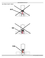
Page 43: ...43 Low Water Cutoff Detail LOW WATER CUTOFF NO NO YES PN 240011430 REV P 09 15 2021 ...
Page 48: ...48 3 FAULT SOLUTION SECTIONS PN 240011430 REV P 09 15 2021 ...


