Ecoflam MULTIFAM 500.1 PRE Manual Download Page 12

!

WARNING:

handling and moving operations must be carried out by specialised personnel.

Use the eyebolts to lift the burner in order that it will not overturn and fall down.

INSTALLATION

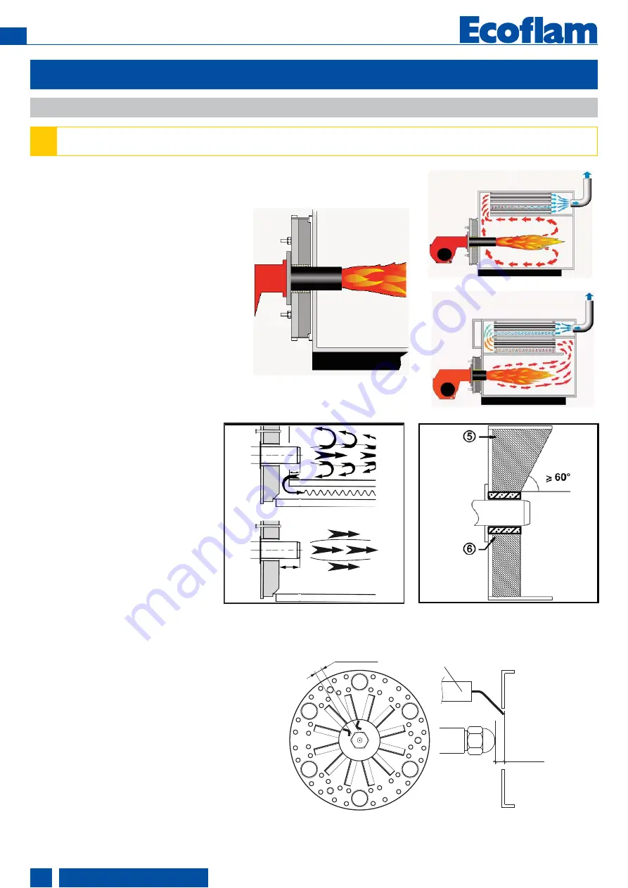
Fitting the burner to the boiler

Position of the electrodes ­ nozzle installation

3 ÷ 4 mm

5 ÷ 6 mm

Ignition Electrode

BURNER LINING
Check before burner installation:

1. Depending on the type of boiler (reverse
flame or three pass) check the burner blast
tube installation depth according to the
data specified by the boiler manufacturer
or consult the burner producer.

2. From the factory the nozzle for
progressive version must be specified from
the customer according to boiler output
and combustion chamber geometry,
otherwise we will select the nozzle for the
80% capacity of the burner.

3. Check the ignition electrodes and the
nozzle on the burner head as per factory
setting (see figures).
The setting of the mixing and ignition unit
according to the boiler output will be
performed during commissioning
procedure.

4. Check that the head is preset at 50%.

420010940500

EN

www.ecoflam­burners.com

12

To perform the installation of the burner
into the boiler drill the boiler plate
according to the dimension given on this
manual and place the burner towards it by
lifting and moving the burner by means of
eyebolts.

Place the gasket on the burner flange and
install the burner into the boiler by fixing
nuts into the bolts.
The space between the blast tube and the
boiler lining must be sealed with
appropriate insulating material.

Burner blast tube insertion depth and
brickwork

Unless otherwise specified by the boiler
manufacturer, heat generators without a
cooled front wall require brickwork or
insulation 5 as shown in the illustration.
The brickwork must not protrude beyond
the leading edge of the blast tube, and
should have a minimum conical angle of
60°. Gap 6 must be filled with an elastic,
non-combustible insulation material. For
boilers with reverse firing, the minimum
burner tube insertion depth A as speci fied
in the boiler manufacturer’s instructions
must be observed.

On boilers the blast tube insertion depth
should be observed as per the boiler
manufacturer's instructions.
Reverse flame boiler :
A = 50-100 mm.
Three pass boilers :
A1 = 50-100 mm.

Exhaust system

To avoid unfavourable noise emissions, 
right-angled connectors should not be 
used on the flue gas side of the boiler.

A

A1

Summary of Contents for MULTIFAM 500.1 PRE

Page 1: ...RE TL LMV51 S 3146127 Technical data Operating instructions Electric diagrams Spare parts list MULTIFLAM 500 1 PRE MULTIFLAM 600 1 PRE Gas train manual is separate www ecoflam burners com GAS HEAVY OI...

Page 2: ...ssure loss diagrams 19 Electrical connections 21 Start up checking procedure recording commissioning data 22 Exhaust gas test 23 Start up oil side 24 Fuel selection Start up 24 Adjusting the max air f...

Page 3: ...el After having removed the packaging check that the contents are in good condition and correspond with what was ordered If in doubt contact the manufacturer The burner must be installed by a qualifie...

Page 4: ...ocal installer in this case to comply to the local safety regulations For burners over 1700 kW gas train connection pipe must be ordered Kits and accessories are managed and delivered separately Compo...

Page 5: ...s train 17 Pilot gas train 18 Oil pressure regulator 19 Gas filter 20 Ball valve 23 Antivibration coupling GTCP Gas train connection pipe POS 1 ON POS 0 OFF 0 I S R SA HLBT HLR HL OIL HL GAS SAMA I 0...

Page 6: ...l gas and dual fuel burners and are available in different con gurations Double gas valves with actuators and regulator VGD Siemens and min pressure switch ACS gas filter 1 2 3 9 11 8 10 5 6 7 Gas gov...

Page 7: ...100 depending on the gas train selected GAS natural pressure mbar 35 500 50 500 LPG pressure mbar 65 500 90 500 Air regulation Type Air flap Air flap Air flap control with servomotor Model SQM45 SQM48...

Page 8: ...8000 kW L flame m 5 m medium value D flame m 1 m medium value WARNING Some flame modifications can be done in our FLEXSHOP in the factory in order to shape the flame and adapt it to some special boil...

Page 9: ...Burner boiler mounting flange Packaging only burner WARNING Please follow the suggested dimension for the hole on the boiler flange in order to fit the burner Make sure that between the boiler and th...

Page 10: ...the mechanical compound control system will be fed with the OPEN or CLOSE signal via the regulator and thus increase or decrease the oil and air flow rates This compound control system will vary the p...

Page 11: ...es flame signal to control box so that the safety shut off valves will be opened The gas will be fed to the gas nozzles via the gas damper while combustion air is supplied by the fan Gas and air will...

Page 12: ...m the installation of the burner into the boiler drill the boiler plate according to the dimension given on this manual and place the burner towards it by lifting and moving the burner by means of eye...

Page 13: ...erature of the heavy oil according to viscosity and the pump pressure according to temperature Ecoflam heavy oil and dual fuel heavy oil burners do have in the electrical panel the fuel temperature de...

Page 14: ...PRESSURE OIL SUCTION PRESSURE The maximum permissible vacuum is 0 4 bar At higher vacuum levels the fuel oil will tend to separate air from oil which may lead to operating trouble In the ring line mod...

Page 15: ...ipe oil pipe oil pipe heating cable insulation section 13 12 LEGENDA 1 Burners 2 Service tank 3 Electric heaters 4 Safety and operation thermostat 5 Level switch working safety 6 Heating coil 7 Self c...

Page 16: ...pump shaft Note for commissioning during commissioning the filter pipelines and pumps must be pre filled with fuel oil and vented The direction of rotation of the motor should be checked When commissi...

Page 17: ...o taking the burner into operation or after any repair work make sure to vent the complete gas feed line and the gas valves and instruments group into the open atmosphere e g by means of a hose taking...

Page 18: ...he head loss diagram is only indicative and does vary depending on the setting of the head PILOT GAS TRAIN CONNECTION The pilot gas train is already installed to the burner and shall be connected to t...

Page 19: ...000 1 PR MULTICALOR 500 1 MULTIFLAM 500 1 VGD 40 125 no yellow 33 500 3C FILTER DN 125 35 500 VGD 40 100 no yellow 40 500 FILTER DN 100 45 500 VGD 40 080 no yellow 60 500 FILTER DN 80 75 500 VGD 40 06...

Page 20: ...LTICALOR 600 1 MULTIFLAM 600 1 VGD 40 125 no yellow 45 500 4C FILTER DN 125 50 500 VGD 40 100 no yellow 55 500 FILTER DN 100 60 500 VGD 40 080 no yellow 80 500 FILTER DN 80 100 500 VGD 40 065 no yello...

Page 21: ...n order to secure the required level of protection All the links power and control are connected to the terminal block of the cabinet Provide cables in sufficient length to secure the rotation of the...

Page 22: ...g level GAS START UP NOTE Adjust the gas unit according to the fuel oil unit Set the fuel selector switch to its Gas position Connect the measuring instruments for the gas head pressure on the test co...

Page 23: ...to be exceeded DETERMINING THE VOLUMETRIC GAS FLOW RATE The thermal furnace output of a boiler QF is the amount of heat supplied with the gas in a unit of time When taking the burner into operation t...

Page 24: ...burner output from the low ame to the high ame and set oil servomotor curve in order to have a stable ame Refer to LMV manual attacched Check the combustion values and adjust the oil pressure Firing...

Page 25: ...w press key F the led Out 1 starts to ash if You need to modify minimum oil temperature press increase or decrease button after confirm the new value pressing again F if you need to modify an other te...

Page 26: ...piping with heavy oil to facilitate the pump priming Start the burner and check the pump feeding pressure In case the pump priming does not take place during the first pre purging with a consequent s...

Page 27: ...ARNING Once the setting on the oil has been completed make sure that you close the manometer pressure switch tap VLO 311 178 180 176 184 186 VL RL CV CV min I I 185 VLO 311 178 180 176 VL RL CV CV max...

Page 28: ...Gradually increase burner output from the low ame to the high ame and set gas servomotor curve in order to have a stable ame Refer to LMV manual attacched The ame stabilisation can be achieved by adju...

Page 29: ...ing the control box rearm button WARNING the air pressure switch shall prevent the air pressure to go below 80 from the adjustment value in order to prevent the CO in the fumes to exceed 1 10000 ppm U...

Page 30: ...d check the gas flow Clean the gas filter cartridge with air periodically replace it if necessary After the cleaning of the components of the gas train perform the leakage test Make visual inspection...

Page 31: ...any intervention as wrong position could cause ignition troubles Check and clean the gas filter in the pilot gas valve 3 4 mm 5 6 mm Ignition Electrode POSITION OF ELECTRODES GAS FILTER CLEANING GAS...

Page 32: ...imiter water failure cut out electrical limit switches etc If the trouble is not found to be due to any of the above mentioned points it will be necessary to test the burner functions very carefully P...

Page 33: ...33 www ecoflam burners com EN 420010940500 APPENDIX Fluidics nozzle chart...

Page 34: ...34 www ecoflam burners com EN 420010940500 APPENDIX Fluidics nozzle chart...

Page 35: ...35 www ecoflam burners com EN 420010940500 APPENDIX Fluidics nozzle chart...

Page 36: ...200 B 20 350 350 350 350 345 345 340 330 325 300 285 275 260 245 220 200 190 200 A 25 65 66 67 68 70 71 73 75 78 81 86 90 95 100 108 115 122 135 150 170 190 200 B 25 400 400 400 400 390 385 380 375 3...

Page 37: ...145 152 162 170 180 195 210 250 290 375 B 20 600 590 580 575 560 550 540 530 515 500 485 465 450 425 400 370 375 A 25 130 130 130 132 134 136 138 140 146 150 155 160 170 180 195 210 230 250 275 320 37...

Page 38: ...20 130 140 150 165 180 200 225 250 280 325 375 440 520 600 B 20 920 900 890 850 820 800 780 760 740 710 690 670 650 610 580 600 A 25 120 125 130 140 150 160 170 180 190 220 240 260 280 330 370 410 460...

Page 39: ...ALLATION Return plugged Inlet end return G 1 2 To nozzle G 1 2 Pressure gauge port G 1 4 Vacuum gauge port G 1 4 40 20 30 35 10 15 25 5 1000 1200 1400 200 400 0 600 800 TA5 TA4 TA3 TA2 0 900 1500 1100...

Page 40: ...40 www ecoflam burners com EN 420010940500 APPENDIX Electrical diagrams...

Page 41: ...41 www ecoflam burners com EN 420010940500 APPENDIX Electrical diagrams...

Page 42: ...IETA RISERVATA DELLA DITTA ECOFLAM S p A DATA FIRMA DATA FIRMA CONTROLLATO DESCRIZIONE MODIFICA DISEGNATO DATA FIRMA COMUNICARE A TERZI IL CONTENUTO DEL PRESENTE A TERMINE DI LEGGE E VIETATO RIPRODURR...

Page 43: ...43 www ecoflam burners com EN 420010940500...

Page 44: ...1 PRE Multiflam 600 1 PRE 7 8 45 28 51 52 59 6 5 65 27 17 46 16 18 15 19 26 50 53 69 59 70 57 55 56 58 43 29 14 31 33 30 35 44 2 32 60 61 61 42 36 41 40 39 38 37 34 63 67 49 30 30 48 48 68 64 1 9 62...

Page 45: ...H Comepi 65324098 65324098 22 GAS HEAVY OIL SELECTOR Comepi a ECX1 65324099 65324099 23 SELECTOR RCK 194L E12 8751 740160016800 740160016800 24 LAMP LYVIA 10X28 BA9S 65324100 65324100 RED LED 65325033...

Page 46: ...65324817 65324817 59 HEATING ELEMENT 50 W 65323072 65323072 60 PILOT GAS VALVE BRAHMA EG12SRGMO 65323595 65323595 61 COIL BRAHMA EG12SR 65323707 65323707 62 GAS GOVERNOR 1 2 FG1B 15 65325207 65325207...

Page 47: ...47 www ecoflam burners com EN 420010940500...

Page 48: ...ul to its products without affecting their main features Ecoflam Bruciatori S p A si riserva il diritto di apportare ai prodotti le modifiche che riterr necessarie o utili senza pregiudicarne le carat...

Reviews: