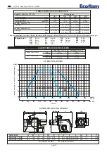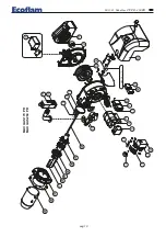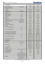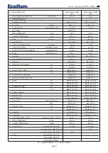
LB 1681
Max Gas 170 PR - 250 PR
B
pag.11
STARTING-UP THE BURNER
PRELIMINARY CHECKS
Before starting up the boiler check the following: - gas type and feed pressure; - gas valves closed; - the seals in the pipe
fittings; - gas pipe breather and input pressure; - that the cable complies with the diagram and the phase and neutral
wires correspond; - that the burner shuts down when the boiler thermostat opens; - the seal of the boiler furnace which
prevents air from entering; - the seal on the flue-boiler pipe fitting; - the condition of the flue (sealed, free from blocka-
ge, etc ). If all these conditions are present, start the burner. The control device starts the motor to carry out prewashing
of the combustion chamber. During this prewash period (about 30 seconds) the device checks that air pressure is cor-
rect via the air pressure switch. At the end, it supplies power to the transformer and opens the gas valves. The flame
must be lit and stabilize within 3 seconds, which is the device's safety time limit. Check to ensure the flame is lit before
placing any control instrument in the flue. Adjust and check the gas flow necessary for the boiler at the meter. Adjust
the air flow according to the gas flow to obtain correct combustion.
IMPORTANT ADVICE
All adjustable parts must be fixed by the installer after making adjustments. Check flue combustion after each adjusti-
ment. The CO
2
values must be approx. 9.7 (G20) 9.6 (G25 11.7 (13B) 11.7 (13P) axld the CO must be less than 75
ppm.
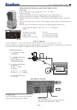
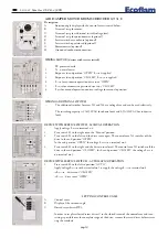
GAS TRAIN INSTALLATION
DUNG
S
1
2
3
4
5
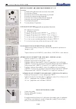
1 - Main valve
2 - Extra safety valve (optional)
3 - Min gas pressure switch
4 - Gas governor and filter
5 - Ball valve
12
24
40
70 100
190
480
1200
2450
0,1
0,2
0,3
0,4
0,5
0,6
1,0
2,0
3,0
4,0
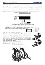
d=0,225
d=0,3
d=0,4
d=0,5
d=0,6
d=0,7
d=0,8
(b)
(a)
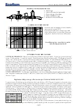
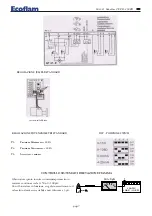
Lunghezza camera di combustione
kW d = diametro camera di combustione
L’installazione deve essere fatta in confor-
mità alle disposizioni locali.
The burners have been certified in combustion cham-
bers according to EN 676 standards. Consult the bur-
ner manufacturer if the combustion chamber of the
boiler in which the burner is to be installed has smal-
ler dimensions.
Installation must be carried out in compliance with the local provisions
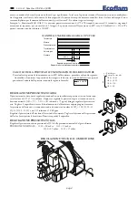
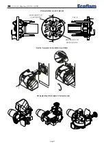
Adjusting the gas flow rate at the ignition for burners MAX GAS 170-250
The thermal power at the ignition, for such a burners, must be smaller than 120 kW or else than the ratio between the
rated thermal power and control box’s safety time (ignition time is assumed equal to safety time, i.e. 3 seconds). The
adjustment of thermal power at the ignition is made by the manufacturer, anyhow, should it be necessary to intervene
on such an adjustment, proceed as follows: - check that the thermal power of the burner at full running is the correct
one. - With the burner switched off, disconnect the flame detection cable from relevant
electrode, so as to make the valve to automatically shut off at the ignition, after the safety
time. - Make a reading on the gas meter. - Start the burner and wait for the burner’s lock
out, after the repetition of the ignition sequence. - Make a second reading on the meter,
and note the number of delivered litres. - The delivered thermal power, at the ignition,
will then be equal to the ratio, between the delivered litres and the safety time, multi-
plied by the F factor (as function of the type of gas used) read on the table at the side. If
the value thus obtained is higher than 120 kW it shall be necessary to reduce the gas valve’s initial flow rate. At the end,
reconnect the flame detection cable to its relevant electrode.
GAS
F
G20 (nat.gas) 34,02
G25
-
G30 (buthane) -
G31 (propane) 88


