Ecoair ECO1850SD Nstallation And Operations Manual Download Page 34

31

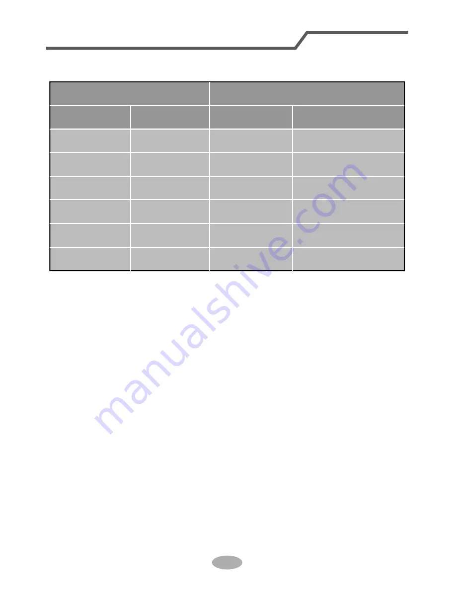
Additional refrigerant charging amount for R22, R407C, R410A and R134a

Diameter of connection pipe

Liquid pipe(mm)

Gas pipe(mm)

ĭ

ĭRUĭ

ĭRUĭ

ĭ

ĭ

ĭ

ĭ

ĭRUĭ

ĭRUĭ

ĭRUĭ

_

_

Cooling only(g/m) Cooling and heating(g/m)

30

120

120

20

Outdoor unit throttle

Configuration of connection pipe

Summary of Contents for ECO1850SD

Page 1: ...ir conditioner Model information can be found on the CE label Please register your product online at www ecoair org For your future convenience record the model information below ____________________________________ MODEL NUMBER ____________________________________ SERIAL NUMBER ____________________________________ PURCHASE DATE ...

Page 2: ...n a safe way and understand the hazards involved Children should not play with the appliance Cleaning and user maintenance shall not b e made by minors without supervision This marking indicates that this product should not be disposed with other household waste throughout the EU To prevent possible harm to the environment or human health from uncontrolled waste disposal recycle it responsibly to ...

Page 3: ...ote control Emergency operation Operation Clean and Maintenance Malfunction Malfunction analysis 13 Installation Notice Installation dimension diagram Tools for installation Selection of installation location Requirements for electric connection Installation Instalation of indoor unit Installation of outdoor unit Vaccum pumping Leakage detection Post Installation checklist Test and Operation Test ...

Page 4: ...ACK 2 The BROWN wire is the LIVE and must be connected to the terminal which is marked with the letter L or coloured RED 3 The GREEN YELLOW is the EARTH and must be connected to the terminal which is marked with the letter E or or coloured GREEN or GREEN YELLOW 4 Always ensure that the cord grip is positioned and fastened correctly If a 13 Amp BS 1363 fused plug is used it must be fitted with a 13...

Page 5: ...DOIXQFWLRQ Ɣ LI WKH XQLW UHTXLUHV UHORFDWLRQ FRQVXOW DQG HQJDJH D TXDOLILHG HQJLQHHU WR DYRLG SHUVRQDO LQMXU DQG XQLW GDPDJH Ɣ R QRW VWHS RQ RU SODFH KHDY REMHFWV RQ WRS RI WKH LQGRRU XQLW DV WKLV PD FDXVH SHUVRQDO LQMXU RU GDPDJH Ɣ QVXUH WKDW RXU DSSOLDFQH LV FRUUHFWO HDUWKHG WR DYRLG HOHFWULFDO VKRFN Ɣ QVWDOO HOHFWULF LVRODWRUV WR DYRLG PDOIXQFWLRQ Ɣ QVWDOODWLRQ DQG PDLQWHQDQFH WR EH SHUIRUPHG E...

Page 6: ...aux button horizontal louvre air outlet heating indicator temp indicator cooling indicator power indicator receiver window drying indicator display remote control air inlet handle air outlet Notice Actual product may be differ from the above graphics please refer to actual products ON OF F TURBO X FAN F C H O U R ONOFF 02 1 6 1 6 3 7 03 7 0 5 21 2 7 7 0 2 ...

Page 7: ...emp Sleep mode Clock Heat mode Fan mode Dry mode Cool mode Auto mode Operation mode I feel 1 1 2 5 4 6 7 8 11 12 13 9 14 15 ON OFF button button 3 SWING button FAN button MODE button I FEEL button optional CLOCK button 10 TIMER ON button TIMER OFF button TURBO button LIGHT button 16 X FAN button optional SLEEP button TEMP button button optional button X fan mode health function 21 2 02 1 6 1 6 3 7...

Page 8: ...in to turn off the unit button 2 Press this button to decrease set temperature Holding it down above 2 seconds rapidly decreases set temperature In AUTO mode set temperature is not adjustable button 3 Press this button to increase the set temperature Holding it down above 2 seconds rapidly increases set temperature In AUTO mode set temperature is not adjustable MODE button 4 Each time you press th...

Page 9: ...this function This function is available in COOL HEAT Only for models with heating function mode to maintain the most comfortable temperature for you SLEEP button 10 TEMP button OFF Press this button to see the indoor set temperature indoor ambient temperature or outdoor ambient temperature on indoor unit s display Temperature is set circularly by remote control as below no display Ɣ KHQ VHOHFWLQJ...

Page 10: ...ff the unit After energization X FAN OFF is defaulted X FAN is not available in AUTO FAN or HEAT mode the display s light If the light is turned on is displayed If the light is turned off disappears reach the preset temperature in the shortest time In COOL mode the unit will blow air at super high fan speed strong cooling air at super high fan speed In HEAT mode the unit will blow strong heating p...

Page 11: ...and buttons About switch between Fahrenheit and Centigrade When the unit is OFF press MODE and buttons simultaneously to switch between ć Combination of TEMP and CLOCK buttons About Energy saving Function Press TEMP and CLOCK simultaneously in COOL mode to start energy saving function Display on the remote control displays SE Repeat the operation to quit the function Combination of TEMP and CLOCK ...

Page 12: ...rrow direction 2 Replace two AAA 1 5V dry batteries and make sure the position of polar and polar are correct 3 Reinstall the cover of battery box Note Ɣ XULQJ RSHUDWLRQ SRLQW WKH UHPRWH FRntrol signal sender at the receiving window on indoor unit Ɣ The distance between signal sender and receiving window should be no more than 8m and there should be no obstacles between them or wireless telephone ...

Page 13: ...ton panel Cleaning and Maintenance Note Ŷ Turn off the air conditioner and disconnect the power before cleaning the air conditioner to avoid electric shock Ŷ R QRW ZDVK WKH DLU FRQGLWLRQHU ZLWK water to avoid electric shock Ŷ R QRW XVH YRODWLOH OLTXLG WR FOHDQ WKH air conditioner Clean surface of indoor unit When the surface of indoor unit is dirty it is recommended to use a soft dry cloth or wet ...

Page 14: ...YDFFXP FOHDQHU RU ZDWHU to clean the filter the water below 45ć to clean it and then air dry in the shade to avoid deformation Note Its good to change filter every 2 years To purchase new filter contact EcoAir or your dealer panel cover tightly Note operation environment cleaning frequency can be increased picture ...

Page 15: ...r corroded If yes please contact dealer 5 Check whether drainage pipe is damaged 1 Disconnect power supply 3 Check whether mounting bracket for outdoor unit is damaged or corroded If yes please contact dealer Notice for recovery 1 Many packing materials are recyclable materials Please dispose them in appropriate recycling unit 2 If you want to dispose the air conditioner please contact local deale...

Page 16: ... PLQ DQG then turn on the unit again Ɣ 6LJQDO UHFHLYLQJ UDQJH LV P Ɣ 5HPRYH REVWDFOHV Ɣ 6HOHFW FRUUHFW DQJOH DQG SRLQW the remote controller at the receiving window on indoor unit Ɣ KHFN WKH EDWWHULHV I WKH SRZHU RI EDWWHULHV DUH WRR ORZ SOHDVH UHSODFH WKHP Ɣ Take the remote control closer to the indoor unit and then try again Ɣ KHFN ZKHWKHU UHPRWH FRQWURO DSSHDUV WR EH GDPDJHG I HV UHSODFH LW 1R ...

Page 17: ...QLW V DLU RXWOHW Ɣ QGRRU WHPSHUDWXUH DQG KXP LGLW LV KLJK Ɣ HFDXVH LQGRRU DLU KDV FRROHG UDSLGO IWHU D ZKLOH LQGRRU WHPSHUDWXUH DQG KXPLGLW ZLOO GHFUHDVH DQG PLVW ZLOO GLVDSSHDU 3KHQRPHQRQ KHFN LWHPV 6ROXWLRQ 6HW WHPSHU DWXUH FDQ W EH DGMXVWHG Ɣ 8QLW LV RSHUDWLQJ LQ DXWR PRGH Ɣ THPSHUDWXUH FDQ W EH DGMX VWHG XQGHU DXWR PRGH 3OHDVH VZLWFK WKH RSHUDWLRQ PRGH LI RX QHHG WR DGMXVW WHPSHUDWXUH Ɣ YRXU U...

Page 18: ...nit again Outdoor unit has vapor Ɣ HDWLQJ PRGH LV WXUQHG RQ Ɣ XULQJ GHIURVWLQJ XQGHU KH ating mode it may generate vapor which is a normal phenomenon ater noise Ɣ Air conditioner is turned on or turned ofI MXVW QRZ Ɣ The noise is the sound of the unit which is a normal phenomenon Cracking noise Ɣ Air conditioner is turned on or turned ofI MXVW QRZ Ɣ This is the sound of friction caused by expansio...

Page 19: ...PD FDXVH Warning UURU FRGH E5 E8 U8 H6 C5 F1 F2 TURXEOHVKRRWLQJ W FDQ EH HOLPLQDWHG DIWHU UHVWDUWLQJ WKH XQLW I QRW SOHDVH FRQWDFW TXDOLILHG DLU FRQGLWLRQLQJ HQJLQHHU IRU VHUYLFH W FDQ EH HOLPLQDWHG DIWHU UHVWDUWLQJ WKH XQLW I QRW SOHDVH FRQWDFW TXDOLILHG DLU FRQGLWLRQLQJ HQJLQHHU IRU VHUYLFH W FDQ EH HOLPLQDWHG DIWHU UHVWDUWLQJ WKH XQLW I QRW SOHDVH FRQWDFW TXDOLILHG DLU FRQGLWLRQLQJ HQJLQHHU IRU...

Page 20: ...e to the obstruction Space to the obstruction Space to the obstruction Space to the obstruction Space to the wall At least 200cm At least 30cm At least 250cm At least 15cm At least 300cm Space to the ceiling Space to the obstruction At least 15cm At least 15cm Space to the wall Space to the wall ...

Page 21: ...ce with high frequency devices such as welding machine medical equipment 3 The place near coast area 4 The place with oil or fumes in the air 5 The place with sulfureted gas 6 Other places with special circums tances 7 The appliance shall not be install ed too close to wet laundry will not affect neighborhood 2 The location should be well ventilated and dry in which the outdoor unit Tools for inst...

Page 22: ... interconnec tion cable away from the copper tube 9 The appliance shall be installed in accordance with national wiring regulations earthed with a specialized earthing device by a qualified electrician Please make sure it is always earthed effectively otherwise it may cause electric shock 2 The yellow green wire in air conditioner is the earth wire which can t be used for other purposes 3 The eart...

Page 23: ...ding to the direction of outlet pipe The position of piping hole should be a little lower than the wall mounted frame shown as below Step three open piping hole 2 Open a piping hole with the diameter oI ĭ RQ WKH VHOHFWHG RXWOHW SLSH position In order to drain smoothly slant the piping hole on the wall slightly downward to the outdoor side with the gradient of 5 10 18K Left Wall ĭ PP Right Mark in ...

Page 24: ...ight please cut off the corresponding hole on the bottom case cut off the hole left right 1 The pipe can be led out in the direction of right rear right left or rear left left rear left right rear right Step four outlet pipe Installation of indoor unit union nut pipe joint pipe Indoor 5 10 outdoor ĭ ĭ Note Ɣ 3D DWWHQWLRQ WR GXVW SUHYHQWLRQ DQG WDNH UHOHYDQW VDIHW PHDVXUHV ZKHQ opening the hole Ɣ 7...

Page 25: ...l remove the screw on the wiring cover and then take wiring cover screw panel Step seven connect wire of indoor unit 4 Wrap the indoor pipe and joint of con then wrap it with tape Step six install drain hose Installation of indoor unit torque wrench open end wrench indoor pipe pipe union nut Hex nut diameter Tightening torque N m ĭ ĭ ĭ ĭ ĭ 30 40 a a a a indoor unit 2 Wrap the joint with tape Note ...

Page 26: ...ing for a new one Avoid extending the wire by yourself installation to building regulations Ɣ RU WKH DLU FRQGLWLRQHU ZLWKRXW D SOXJ D spur switch must be installed in the line 3 Remove the wire clip connect the power connection wire to the wiring terminal according to the colour tighten the screw with wire clip power connection wire cable cross hole 2 Make the power connection wire go through the ...

Page 27: ... should be bound separately at the end Note Ɣ The power cord and control wire can t be crossed or winding Ɣ The drain hose should be bound at the bottom drain hose band connection pipe indoor power cord Step nine hanging the indoor unit 1 Pass the pipes through the wall hole first 2 Hang the indoor unit on the wall mounting frame 3 Stuff the gap between pipes and wall hole with sealing gum 4 Fix t...

Page 28: ...alled at least joint Ɣ RU WKH XQLW ZLWK FRROLQJ FDSDFLW RI a 6 expansion bolts are needed IRU WKH XQLW ZLWK FRROLQJ FDSDFLW RI a 8 expansion bolts are needed IRU WKH XQLW ZLWK FRROLQJ FDSDFLW RI a H SDQVLRQ EROWV DUH QHHGHG Step two install drain joint g n i t a e h d n a g n i l o o c r o f y l n O unit 1 Connect the outdoor drain joint into the hole on the chassis as shown in the picture below 2...

Page 29: ...en the union nut with torque wrench by referring to the sheet below screw gas pipe liquid pipe liquid valve gas valve union nut pipe joint Hex nut diameter Tightening torque N m ĭ ĭ ĭ ĭ ĭ 30 40 a a a a 1 Remove the wire clip connect the power connection wire and signal control wire only for cooling and heating unit to the wiring terminal according to the colour fix them with screws Indoor unit con...

Page 30: ...e higher than the outlet pipe hole of indoor unit Ɣ 6ODQW WKH GUDLQ KRVH VOLJKWO GRZ nwards The drain hose can t be Ɣ The water outlet can t be placed in water in order to drain smoothly Installation of outdoor unit U shaped curve wall drain hose the drain hose can t raise upwards The drain hose can t be fluctuant The drain hose can t be fluctuant The water outlet can t be fluctuant The water outl...

Page 31: ...o leak remove the piezometer open the valve core of liquid valve and gas valve completely with inner hexagon spanner 6 7 Reinstall the handle Tighten the screw caps of valves and refrigerant charging vent Use vacuum pump liquid valve gas valve refrigerant charging vent cap of refrigerant charging vent vacuum pump piezometer valve cap Lo Hi inner hexagon spanner open close 1 With leakage detector C...

Page 32: ...Does the power cord follow the speci It may cause malfunction or damaging the parts Is there any obstruction in the air inlet and outlet heating capacity The dust and sundries caused during installation are removed It may cause malfunction or damaging the parts The gas valve and liquid valve of connection pipe are open completely heating capacity 1 Preparation of test operation Ɣ The client approv...

Page 33: ...HIULJHUDQW FKDUJLQJ DPRXQW SHU PHWHU LV GLfIHUHQW DFFRUGLQJ WR WKH GLDPHWHU RI OLTXLG SLSH 6HH WKH following sheet GGLWLRQDO UHIULJHUDQW FKDUJLQJ DPRXQW H WHQGHG OHQJWK RI OLTXLG SLSH î DGGLWLRQDO UHIULJHUDQW FKDUJLQJ DPRXQW SHU PHWHU Cooling capacity Cooling capacity WX K WX K WX K WX K WX K WX K WX K WX K WX K WX K Max height difference Max height difference Max length of connec tion pipe Max le...

Page 34: ...for R22 R407C R410A and R134a Diameter of connection pipe Liquid pipe mm Gas pipe mm ĭ ĭ RU ĭ ĭ RU ĭ ĭ ĭ ĭ ĭ ĭ RU ĭ ĭ RU ĭ ĭ RU ĭ _ _ Cooling only g m Cooling and heating g m 30 120 120 20 Outdoor unit throttle Configuration of connection pipe ...

Page 35: ...ting pipe D Put on the union nut Ɣ 5HPRYH WKH XQLRQ QXW RQ WKH LQGRRU connection pipe and outdoor valve install the union nut on the pipe union pipe pipe E Expand the port Ɣ SDQG WKH SRUW ZLWK H SDQGHr Note Ɣ LV GLfferent according to the diameter please refer to the sheet below expander hard mold pipe F Inspection Ɣ KHFN WKH TXDOLW RI H SDQGLQJ SRUW I WKHUH LV DQ EOHPLVK H SDQG WKH port again acc...

Page 36: ...RRANTY VOID The actual product may differ slightly from the illustration This warranty is in addition to and does not affect your statutory rights For further information please contact 0845 388 0007 This product has been manufactured to comply with the EC Directives 2006 95 EC and 2004 108 EC SERVICE AND WARRANTY ONE 1 YEAR LIMITED WARRANTY Save This Warranty Information ments Copyright Reserved ...

Reviews: