background image

Modbus Read, Write and Override Parameters plus Exception Codes 

108 

UDC2500 Universal Digital Limit ControllerProduct Manual 

8/05 

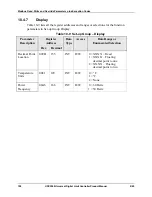
10.4.7 Display 

Table 10-9 lists all the register addresses and ranges or selections for the function 
parameters in Set-up Group Display.  

Table 10-9  Set-up Group – Display 

Parameter 

Description 

Register 

Address 

Data 

Type 

Access 

Data Range or 

Enumerated Selection 


Hex 

Decimal 


Decimal Point 
Location 


009B 155 

INT  R/W  0 = XXXX – Fixed 

1 = XXX.X – Floating 

decimal point to one 

2 = XX.XX – Floating 

decimal point to two 

Temperature 
Units 

0081 129 

INT R/W  0 = °F 

1 = °C 
2 = None 

Power 
Frequency 

00A6 

166 

INT 

R/W 

0 = 60 Hertz 

1 = 50 Hertz 


Summary of Contents for UDC2500 Limit

Page 1: ...Eclipse Universal Digital Controller UDC2500 Limit Control Model 08 2005 Information Guide 925 1...

Page 2: ...ii UDC2500 Universal Digital Limit ControllerProduct Manual 8 05...

Page 3: ...comply with these instructions could result in death or serious injury ATTENTION Electrostatic Discharge ESD hazards Observe precautions for handling electrostatic sensitive devices Protective Earth...

Page 4: ...l Considerations 16 2 7 Wiring Diagrams 18 2 8 Limit Control Application Diagram 25 3 CONFIGURATION 26 3 1 Overview 26 3 2 Configuration Prompt Hierarchy 27 3 3 Configuration Procedure 28 3 4 Lock Set...

Page 5: ...69 7 TROUBLESHOOTING SERVICE 71 7 1 Overview 71 7 2 Troubleshooting Aids 72 7 3 Power up Tests 74 7 4 Status Tests 74 7 5 Background Tests 75 7 6 Controller Failure Symptoms 77 7 7 Troubleshooting Pro...

Page 6: ...100 10 4 1 Lock 100 10 4 2 Limit 101 10 4 3 Input 1 102 10 4 4 Options 104 10 4 5 Communications 105 10 4 6 Alarms 106 10 4 7 Display 108 10 5 Modbus RTU Exception Codes 109 11 ETHERNET TCP IP 111 11...

Page 7: ...es _______________ 56 Table 5 2 Equipment Needed__________________________________________________________ 58 Table 5 3 Set Up Wiring Procedure for Thermocouple Inputs Using an Ice Bath ______________...

Page 8: ...___ 99 Table 10 2 Miscellaneous Read Onlys___________________________________________________ 99 Table 10 3 Set up Group Lock________________________________________________________ 100 Table 10 4 Set...

Page 9: ...ommunications Option Connections __________________________________ 23 Figure 2 12 Auxiliary Output and Digital Inputs Option Connections __________________________ 24 Figure 2 13 Transmitter Power fo...

Page 10: ......

Page 11: ...keyboard or from a remote location Contact Input Option The contact of the output relay terminates at the rear terminal of the controller to which you make the appropriate field wiring connections A...

Page 12: ...input and range configuration set the operating parameters that meet you process control needs now and change them later to meet new ones Mount anywhere This instrument is intended for industrial cont...

Page 13: ...on Used in conjunction with the SET UP key to select the individual functions of a selected Configuration Set Up group Used during field calibration procedure Lower Display Lower Display Lower Display...

Page 14: ...ive software program running on either a Pocket PC a Desktop or a laptop computer Create edit configurations live just connect software to controller via comm port Create edit configurations offline a...

Page 15: ...oad a configuration from an instrument You can then save the configuration file onto your PC or pocket PC for review modification or archiving Furthermore this software also gives you important mainte...

Page 16: ...61326 emissions Industrial Equipment EN61326 immunity Method of EMC Assessment Technical File TF Declaration of Conformity 51453655 Deviation from the installation conditions specified in this manual...

Page 17: ...at s in this section The following topics are covered in this section TOPIC See Page 2 1 Overview 7 2 2 Condensed Specifications 8 2 3 Model Number Interpretation 11 2 4 Control and Alarm Relay Contac...

Page 18: ...Temperature Stability 0 01 of Full Scale span C change typical Input Impedance 4 20 Milliampere Input 250 ohms 0 10 Volt Input 200K ohms All Others 10 megohms Maximum Lead Wire Resistance Thermocouple...

Page 19: ...olated from all other circuits at 850Vdc for 2 seconds AC Power is electrically isolated from all other inputs and outputs to withstand a HIPOT potential of 1900Vdc for 2 seconds per Annex K of EN6101...

Page 20: ...to 55 10 to 90 5 to 90 5 to 95 Vibration Frequency Hz Acceleration g 0 0 0 to 70 0 4 0 to 200 0 6 0 to 200 0 5 Mechanical Shock Acceleration g Duration ms 0 0 1 30 5 30 20 30 Line Voltage Vdc 24 1 22...

Page 21: ...0 Base T Ethernet Modbus RTU Plus Auxiliary Output Digital Inputs 3 _ _ _ _ L _ _ No Selection _ _ 0 _ _ _ _ 0 _ _ _ R Availability Software Selections Limit Controller Communications None Infrared in...

Page 22: ...ontroller Restrictions Comments 1 FM approved units with communications are limited to read only 2 FM approved units are restricted to TC and RTD type inputs 3 UL listed for regulatory use only Input...

Page 23: ...iring Relay Contact Indicators Relay Contact Indicators N O Open Open Off N C Closed Off Closed Off N O Closed Open On N C Open Off Closed On Alarm Relays ATTENTION Alarm relays are designed to operat...

Page 24: ...panel cutout requirements for mounting the controller are shown in Figure 2 2 The controller s mounting enclosure must be grounded according to CSA standard C22 2 No 0 4 or Factory Mutual Class No 38...

Page 25: ...red Insert the prongs of the clips into the two holes in the top and bottom center of the case Figure 2 3 For water protected installation four mounting clips are required There are two options of whe...

Page 26: ...d in close proximity to the controller within easy reach of the OPERATOR The switch or circuit breaker shall be marked as the disconnecting device for the controller CAUTION Applying 90 264 Vac to an...

Page 27: ...t metal trays Use Suppression Devices For additional noise protection you may want to add suppression devices at the external source Appropriate suppression devices are commercially available ATTENTIO...

Page 28: ...number select the appropriate wiring diagrams from the composite wiring diagram below Refer to the individual diagrams listed to wire the controller according to your requirements L1 L2 N 4 5 6 Auxili...

Page 29: ...ontroller enclosure to local ground using a No 12 4 mm 2 copper conductor is recommended Before powering the controller see Prelimnary Checks in this section of the Product Manual 1 It is the user s r...

Page 30: ...0 20 mA applications the resistor should be located at the transmitter terminals if Burnout detection is desired 1 2 Splice and tape this junction between the two thermocouples This junction may be lo...

Page 31: ...ltage across both ends of the load even if the relay is turned off Use a dummy resistor as shown to counteract this The total current through the resistor and the the load must exceed 20 mA Solid Stat...

Page 32: ...N Open collector outputs are internally powered at 30 Vdc Connecting an external power supply will damage the controller 1 To terminal 4 or 6 Relay Load To terminal 7 or 9 Relay Load 2 2 Load Supply P...

Page 33: ...maximize performance 3 3 1 Do not run the communications lines in the same conduit as AC power Correct connections may require the use of an Ethernet cross over cable COMMUNIC ATION MASTER OR SWITCH...

Page 34: ...ital Inputs 12 13 xxxx Figure 2 12 Auxiliary Output and Digital Inputs Option Connections Configure A2S1TY NONE A2S2TY NONE 2 Wire Transmitter _ INPUT 1 OUTPUT 3 250 xxxx 26 27 5 6 If necessary instal...

Page 35: ...re 2 14 Transmitter Power for 4 20 mA 2 Wire Transmitter Using Auxiliary Output 2 8 Limit Control Application Diagram Limit Controller Wiring Figure 2 15 shows the RIGHT and WRONG way to wire your Lim...

Page 36: ...iguration data Set Up prompts you are working with and also the specific parameters Function prompts associated with each group Table 3 1 shows an overview of the prompt hierarchy as it appears in the...

Page 37: ...LOCK SECUR LOCK LIMIT LOorHI POWRUP SPMAX SPMIN DISPLY INPUT1 IN1TYP XMITR1 IN1 HI IN1 LO BIAS 1 FILTR1 BRNOUT EMISS OPTIONS DIGIN1 AUXOUT COM ComADR ComSTA IRENAB BAUD SDENAB SHDTIM BAUD TX DLY WS FL...

Page 38: ...e that describes the group of parameters you want to configure Then proceed to the next step 3 Select a Function Parameter Function Function Function Upper Display the current value or selection for t...

Page 39: ...other configuration data has been loaded Function Prompts Table 3 4 LOCK Group Function Prompts Function Prompt Lower Display Selection or Range of Setting Upper Display Parameter Definition SECUR 0...

Page 40: ...POWRUP RST NORM RST after power down the controller latching relay will have to be reset NORM after power down the controller will operate normally in the same mode as before power was removed unless...

Page 41: ...ple High E L E Thermocouple Low J H J Thermocouple High J M J Thermocouple Med J L J Thermocouple Low K H K Thermocouple High K M K Thermocouple Med K L K Thermocouple Low NNMH Ni Ni Moly Thermocouple...

Page 42: ...ents a type K H thermocouple then configure K H and the controller will characterize the 4 to 20 mA signal so that it is treated as a type K thermocouple input high range Parameter definitions are the...

Page 43: ...filter is provided for Input 1 to smooth the input signal You can configure the first order lag time constant from 1 to 120 seconds If you do not want filtering enter 0 BURNOUT PROTECTION SENSOR BREAK...

Page 44: ...r Range of Setting Upper Display Parameter Definition EMISS 0 01 to 1 00 EMISSIVITY is a correction factor applied to the Radiamatic input signal that is the ratio of the actual energy emitted from th...

Page 45: ...e selections 4mA VAL and 20mA VAL ATTENTION Output cannot be configured when Three Position Step Control is used NONE NO AUXILIARY OUTPUT PROC PROCESS VARIABLE Represents the value of the Process Vari...

Page 46: ...g units to represent all AUX OUT parameters except output Use a value in percent for Output Output can be between 5 and 105 CRANGE 4 20 0 20 AUXILIARY OUTPUT RANGE allows the user to easily select 4 2...

Page 47: ...for short link lengths and 15 drops being the maximum at the maximum link length ATTENTION FM Models cannot have parameters changed write transactions via communications parameters can only be change...

Page 48: ...Periods SHED TIME The number that represents how many sample periods there will be before the controller sheds from communications Each period equals 1 3 seconds 0 equals No shed Note If ComSTA is set...

Page 49: ...999 to 9999 COMPUTER SETPOINT RATIO Computer setpoint ratio in Engineering Units LOOPBK DIS ENAB LOCAL LOOPBACK tests the communications hardware DISABLE Disables the Loopback test ENABLE Allows loop...

Page 50: ...alarm setpoint See Table 2 3 in the Installation section for Alarm relay contact information The prompts for the Alarm Outputs appear whether or not the alarm relays are physically present This allow...

Page 51: ...whether you want the alarm type chosen in prompt A1S1TYPE to alarm High or Low HIGH ALARM LOW ALARM A1S2TY ALARM 1 SETPOINT 2 TYPE Select what you want Setpoint 2 of Alarm 1 to represent The selectio...

Page 52: ...STATE Same as A1S1HL ALHYST 0 0 to 100 0 of span or full output as appropriate ALARM HYSTERESIS A single adjustable hysteresis is provided on alarms such that when the alarm is OFF it activates at ex...

Page 53: ...1 only AL 2 Blocks alarm 2 only AL12 Blocks both alarms ATTENTION When enabled on power up or initial enabling via configuration the alarm will not activate unless the parameter being monitored has no...

Page 54: ...ON Auto ranging will occur for selections of one or two decimal places For example should the instrument be configured for two decimal places and the PV exceeds 99 99 then the display will change to a...

Page 55: ...K _______ _______ _______ _______ _______ _______ _______ _______ _______ _______ 3 DIS ENAB ENAB 10 19200 30 FP_B PCT DIS INPUT1 IN1TYP XMITR1 IN1 HI IN1 LO BIAS 1 FILTR1 BRNOUT EMIS FREQ DISPLY ____...

Page 56: ...ontroller including an Operator Interface overview how to lockout changes to the controller entering a security code and monitoring the displays What s in this section The following topics are covered...

Page 57: ...e number 0 to 9999 may be required to change from one level of lockout to another When a controller leaves the factory it has a security code of 0 which permits changing from one lockout level to anot...

Page 58: ...ia keyboard of certain functions or parameters by unauthorized personnel Lockout levels There are different levels of Lockout depending on the level of security required These levels are NONE No Locko...

Page 59: ...1 let you see what is happening to your process and how the Limit Controller is responding The Limit Controller is a single line display device except when in the SETUP mode or the LOWER DISPLAY key i...

Page 60: ...greater than high limit for PV or SP IN1RNG Input 1 Out of Range Out of range criteria Linear range 10 out of range Characterized range 1 out of range PV LIM PV Out of Range PV PV PV bias FAILSF Fails...

Page 61: ...and type Limit Control Type high or low External Reset Contact Input enable or disable Power up Logic Reset relay on or Normal same as before power down Lockout selection Power Up Logic Configurable p...

Page 62: ...splay Lower Display Lower Display Press the Lower Display key till SP appears 2 Enter the Limit Setpoint or Set the SP using the Up Down arrow keys to the desired Limit Setpoint 3 Store the limit setp...

Page 63: ...Input Option External Reset The Contact Input option detects the state of external contacts On contact closure the controller will reset the latching relay if the controller has External Reset enable...

Page 64: ...ints two for each alarm The type and state High or Low is selected during configuration See Subsection 3 Configuration for details Alarm Setpoints Display Table 4 5 Procedure for Displaying Alarm Setp...

Page 65: ...eady for configuration by the user Field Calibration can improve the accuracy of the Controller if necessary for a particular application CAUTION The field calibration will be lost if a change in inpu...

Page 66: ...d separately Select the Voltage Current or Resistance equivalents for 0 and 100 range values from Table 5 1 Use these values when calibrating your controller Table 5 1 Voltage Milliamp and Resistance...

Page 67: ...1200 184 to649 184 to149 184 to649 184 to649 25 202 ohms 25 202 ohms 50 404 ohms 126 012 ohms 329 289 ohms 156 910 ohms 658 578 ohms 1646 445 ohms Linear Milliamps 4 to 20 mA 0 to 20 mA 4 00 mA 0 00 m...

Page 68: ...the controller input Two insulated copper leads for connecting the thermocouple extension wire from the ice baths to the mV source Two containers of crushed ice Thermocouple Inputs T C Source A calibr...

Page 69: ...re for Thermocouple Inputs Using an Ice Bath Step Action 1 Connect the copper leads to the calibrator 2 Connect a length of thermocouple extension wire to the end of each copper lead and insert the ju...

Page 70: ...terminals for Input 1 as shown in Figure 5 3 Thermocouple Source Thermocouple Extension Wire _ 26 27 _ Figure 5 3 Wiring Connections for Thermocouple Inputs Using Thermocouple Source RTD Inputs Refer...

Page 71: ...0 Volts Step Action 1 Connect the copper leads from the calibrator to the Input 1 terminals as shown in Figure 5 5 2 Place current voltage source at zero before switching on 3 Do not switch current vo...

Page 72: ...ource ON OFF while connected to the instrument Volt Source _ 1 2 3 100K pair 26 27 Figure 5 6 Wiring Connections for 0 to 10 Volts Milliamperes Refer to Figure 5 5 and wire the controller according to...

Page 73: ...are also listed Table 5 9 Input 1 Calibration Procedure Step Operation Press Result 1 Enter Calibration Mode Setup Setup until you see Upper Display CAL Lower Display INPUT1 Function Function Functio...

Page 74: ...nt reading of the temperature as measured at the thermocouple terminals and recognized by the controller You can change this value if it is in error using the or keys WARNING The accuracy of the contr...

Page 75: ...ad write except Calibration CONF configuration parameters are Read Only no writes permitted Lower Display LOCK or Until NONE is in the upper display 2 Enter INPUT 1 Setup Group Setup Setup until you s...

Page 76: ...Input Calibration 66 UDC2500 Universal Digital Limit ControllerProduct Manual 8 05...

Page 77: ...MED BY QUALIFIED SERVICE PERSONNEL MORE THAN ONE SWITCH MAY BE REQUIRED TO DE ENERGIZE UNIT BEFORE CALIBRATION 6 2 Auxiliary Output Calibration Introduction Calibrate the controller so that the auxili...

Page 78: ...r and allow the controller to warm up 30 minutes before you calibrate 2 Set LOCK in the Tuning Set Up group to NONE 3 Tag and disconnect the field wiring at the rear of the controller from terminals 1...

Page 79: ...er use the values shown below depending on the action of your controller 3 Calibrate 100 Function Function Function To store the 0 value you will see Upper Display A Value Lower Display SPNVAL or unti...

Page 80: ...arameters can be viewed ALL Tuning and Setpoint Ramp parameters are available for read only No other parameters can be viewed Lower Display LOCK or Until NONE is in the upper display 2 Enter OUTPUT or...

Page 81: ...olve them What s in this section The following topics are covered in this section TOPIC See Page 7 1 Overview 71 7 2 Troubleshooting Aids Overall Error Messages Controller Failure Symptoms Customer Su...

Page 82: ...the local sales office Hardware and software related problems Use the troubleshooting error message prompts and controller failure symptoms to identify typical failures which may occur in the controll...

Page 83: ...fying the Software Version Step Operation Press Result 1 Select STATUS Set Up Group Setup Setup Upper Display READ Lower Display STATUS 2 Read the software version Function Function Function You will...

Page 84: ...hen DONE will appear in the lower display 7 4 Status Tests Introduction When required the results of these tests can be checked to determine the reason the controller has gone to Failsafe How to check...

Page 85: ...ror message shows whenever the controller goes into a failsafe mode of operation This will happen if RAM test failed Configuration test failed Calibration test failed Burnout configured for none and t...

Page 86: ...is a warning message that the controller has detected that the thermocouple is starting to burnout This error message may also be created if the resistance of the wires used to connect the thermocoup...

Page 87: ...disagrees with controller output OK Controller Output disagrees with displayed output Relay Output 2 OK OK OK External Alarm function does not operate properly Malfunction in alarm output 3 Display d...

Page 88: ...t or where to find the data needed to accomplish the task WARNING SHOCK HAZARD TROUBLESHOOTING MAY REQUIRE ACCESS TO HAZARDOUS LIVE CIRCUITS AND SHOULD ONLY BE PERFORMED BY QUALIFIED SERVICE PERSONNEL...

Page 89: ...easure the AC voltage across terminals L1 and L2 on the rear terminal panel of the controller Check the earth ground connection 2 Make sure the chassis plugs into the rear of the case properly Withdra...

Page 90: ...n Procedure 3 Table 7 7 explains how to troubleshoot Alarm Relay Output failure Table 7 7 Troubleshooting Alarm Relay Output Failure Step What to do How to do it 1 Check the alarm configuration data I...

Page 91: ...e connection 2 Controller Keyboard or specific keys may be LOCKED OUT via the security code Use your four digit security code number to change the lockout level Refer to Section 3 Configuration 3 Run...

Page 92: ...r Withdraw the chassis from the case and inspect the board See the exploded view Figure 8 1 for location of the board Return the chassis to the case 3 Determine if the Communications board is faulty b...

Page 93: ...If so then as Auxiliary Ouptut and Digital Input 2 are mutually exclusive you must chose which one of these features you wish to use Make the Options Set UP group function prompt CRANGE 4 20 or 0 20 p...

Page 94: ...1 Turn off the power to the instrument for at least five seconds 2 Turn the power back on and simultaneously press the FUNCTION and buttons This must be done while TEST DONE is being displayed 3 If s...

Page 95: ...rts List 8 1 Exploded View Introduction Figure 8 1 is an exploded view of the UDC2500 Controller Each part is labeled with a key number The part numbers are listed by key number in Table 8 1 Parts not...

Page 96: ...xiliary Output Digital Input Ethernet Communications PWA 5 51452801 504 MCU Inputs PWA with IR for Limit Controllers 6 30755306 501 30756679 501 30756725 501 Output 1 Electro Mechanical Relay Open Col...

Page 97: ...to pry the side tabs from the front face Pry just enough to release it otherwise you ll bend or break the tab If you break or bend the tab and can t reattach the front snugly you ll need to reattach...

Page 98: ...des to provide access to process related information Several MODICON function codes are implemented It is appropriate to define instrument specific user defined function codes Where differences occur...

Page 99: ...t Parameter Type Register Numbers Dec Name Access Notes 1 Type 2 NOT SUPPORTED IEEE Floating Point 2 Attribute NOT SUPPORTED 1 Read Only 2 Read Write 3 Value float high word Read Write 4 Value float l...

Page 100: ...h block reference follow Request Message Format Slave Address Byte Count Reference Type Function Code 14 Reference Type File Number Register Count Register Address Reference Type File Number Register...

Page 101: ...ructure tables on page 3 Although the register address structure tables indicate up to 13 data registers are available for access only register address 3 is currently supported Register Address The re...

Page 102: ...00 02 CRC16 Where 02 Address 14 Function Code 20 14 hex 07 Byte Count 06 Reference Type 00 03 File Number Access Data Value 00 01 Register Address Standard Access Gain 1 Tag ID 1 00 02 Register Count...

Page 103: ...Access LSP 1 ID Tag 39 00 02 Register Count to read Floating Point Data 06 Reference Type IEEE Floating Point 00 03 File Number Access Data Value 00 35 Register Address Standard Access LSP 2 ID Tag 53...

Page 104: ...e 100 000 write limit of the EEROM Request and Response Formats The Request and Response formats for Function code 21 15 Hex are shown below Details for each block reference follow Request Message For...

Page 105: ...ess es See Section 10 for the tag ID numbers Table 9 4 Register Address Format for Function Code 21 Register Address es Dec Register Address es Hex Format 001 to 125 0001 to 007D analog formatted data...

Page 106: ...1 1 5 ID Tag 1 02 15 0B 06 00 03 00 01 00 02 3F C0 00 00 CRC16 Where 02 Address 15 Function Code 21 15 Hex 0B Byte Count 06 Reference Type IEEE Floating Point 00 03 File Number Access Data Value 00 01...

Page 107: ...ontroller Each type of parameter has the identifying codes listed with it What s in this section The following topics are covered in this section TOPIC See Page 10 1 Overview 97 10 2 Reading Control D...

Page 108: ...ated via communications the non volatile memory is updated as soon as the message is received Communications Transfer Rates Reads minimum 20mS and writes minimum 200mS Supported Function Codes IR port...

Page 109: ...gister Address Data Type Access Data Range or Enumerated Selection Hex Decimal Input 1 7B 123 FP RD In Engineering Units or Percentage LSP1 27 30 FP R W In Engineering Units Within Set point Limits 10...

Page 110: ...g or Writing Do a Read or Write depending on your requirements using the identifying code and format code listed in the tables The range or selection available for each range is listed in the tables 1...

Page 111: ...up Limit Table 10 4 Set up Group Limit Parameter Description Register Address Data Type Access Data Range or Enumerated Selection Hex Decimal High Low Limit 0088 136 INT R W 0 Low Limit 1 High Limit P...

Page 112: ...x Decimal Input 1 Type 009F 159 INT R W 1 B TC 2 E TC H 3 E TC L 4 J TC H 5 J TC M 6 J TC L 7 K TC H 8 K TC M 9 K TC L 10 NNM H 11 NNM L 12 Nicrosil H TC 13 Nicrosil L TC 14 R TC 15 S TC 16 T TC H 17...

Page 113: ...icrosil L TC 13 R TC 14 S TC 15 T TC H 16 T TC L 17 W TC H 18 W TC L 19 100 PT RTD 20 100 PT LO RTD 21 200 PT RTD 22 500 PT RTD 23 Radiamatic RH 24 Radiamatic RI 25 Linear 26 Square Root Input 1 High...

Page 114: ...arameter Description Register Address Data Type Access Data Range or Enumerated Selection Hex Decimal Auxiliary Output 009E 158 INT R W 0 None 1 Not Used 2 Not Used 3 PV Low Scaling Factor 0031 049 FP...

Page 115: ...Selection Hex Decimal Communication Address 004D 77 FP R W 1 99 Communications Type 00E7 231 INT R W 0 None 1 Disable 2 RS 485 Modbus 3 Ethernet IRPort Enable 00F1 241 INT R W 0 Disable 1 Enable BaudR...

Page 116: ...Used 8 Not Used 9 Not Used 10 T C Warning 11 Failsafe or T C Fail 12 PV Rate of Change 13 Alarm on Digital Input Alarm 1 Setpoint 1 Value 0009 009 FP R W Within the range of selected parameter or PV...

Page 117: ...gh Alarm Alarm 2 Setpoint 1 Event 0091 145 INT R W 0 Low Alarm 1 High Alarm Alarm 2 Setpoint 2 Event 0093 147 INT R W 0 Low Alarm 1 High Alarm Alarm Hysteresis 0029 041 FP R W 0 0 to 100 of output or...

Page 118: ...the function parameters in Set up Group Display Table 10 9 Set up Group Display Parameter Description Register Address Data Type Access Data Range or Enumerated Selection Hex Decimal Decimal Point Loc...

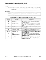
Page 119: ...equest is to a non existent coil or register The slave will return with an exception response informing the master of the nature of the error Illegal Data Address The exception response message has tw...

Page 120: ...addressed device 02 Illegal Data Address The address referenced in the function dependent data section of the message is not valid in the addressed device 03 Illegal Data Value The value referenced a...

Page 121: ...s shipped from the Factory The MAC address is printed on the case label of each instrument When constructing a network it is recommended that a Switch be used to connect UDCs to a LAN rather than usin...

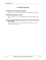
Page 122: ...ment 51 52 25 66 Modbus RTU Serial Communications User Manual 12 2Modbus Messaging on TCP IP Refer to document 51 52 25 121 MODBUS Messaging on TCP IP Implementation Guide 12 3How to Apply Digital Ins...

Page 123: ...meters 100 Configuration Procedure 28 Configuration Prompt Hierarchy 27 Configuration Record Sheet 45 Contact Input 53 Control Relays 13 Control Alarm Circuit Wiring 16 Controller Failure Symptoms 77...

Page 124: ...nd Override Parameters 97 Modbus RTU Function Codes 88 Model Number Interpretation 11 Monitoring your Limit Controller 49 Mounting 14 Mounting Method 15 Mounting Procedure 15 N Non Volatile Memory Ret...

Page 125: ...ay 49 TransmitDelay 105 Transmitter Characterization 32 Troubleshooting Aids 72 Troubleshooting Procedures 78 Troubleshooting Service 71 TX Delay 38 U UDC2500 Limit Controllers 1 V Vibration 10 Viewin...

Page 126: ......

Page 127: ......

Page 128: ......

Reviews: