Modbus Read, Write and Override Parameters plus Exception Codes
8/05
UDC2500 Universal Digital Limit ControllerProduct
Manual
107
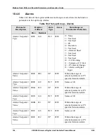
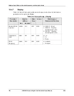
Parameter
Register
Address
Data
Type
Access
Data Range or
Enumerated Selection
Hex
Decimal
Alarm 1 Setpoint 1
Event
008D 141
INT
R/W
0 = Low Alarm
1 = High Alarm
Alarm 1 Setpoint 2
Event
008F
143
INT
R/W
0 = Low Alarm
1 = High Alarm
Alarm 2 Setpoint 1
Event
0091
145
INT
R/W
0 = Low Alarm
1 = High Alarm
Alarm 2 Setpoint 2
Event
0093
147
INT
R/W
0 = Low Alarm
1 = High Alarm
Alarm Hysteresis
0029
041
FP
R/W
0.0 to 100% of output or
span
Alarm Latching for
Output 1
00C8 200
INT
R/W
0 = Non Latching
1 = Latching
Alarm States
00C9 201
INT
R/W
State = 0 = Not in Alarm
State = 1 = In Alarm
Bit 0 = Alarm 11 State
Bit 1 = Alarm 12 State
Bit 2 = Alarm 21 State
Bit 3 = Alarm 22 State
Alarm 1 Blocking
00CA 202
INT
R/W
0 = Disable
1 = AL1
2 = AL 2
3 = AL 1 2
Diagnostic Alarm
009A 154
INT
R/W
0 = Disable
1 = Alarm 1
2 = Alarm 2
Summary of Contents for UDC2500 Limit
Page 2: ...ii UDC2500 Universal Digital Limit ControllerProduct Manual 8 05...
Page 10: ......
Page 76: ...Input Calibration 66 UDC2500 Universal Digital Limit ControllerProduct Manual 8 05...
Page 126: ......
Page 127: ......
Page 128: ......


