background image


18 

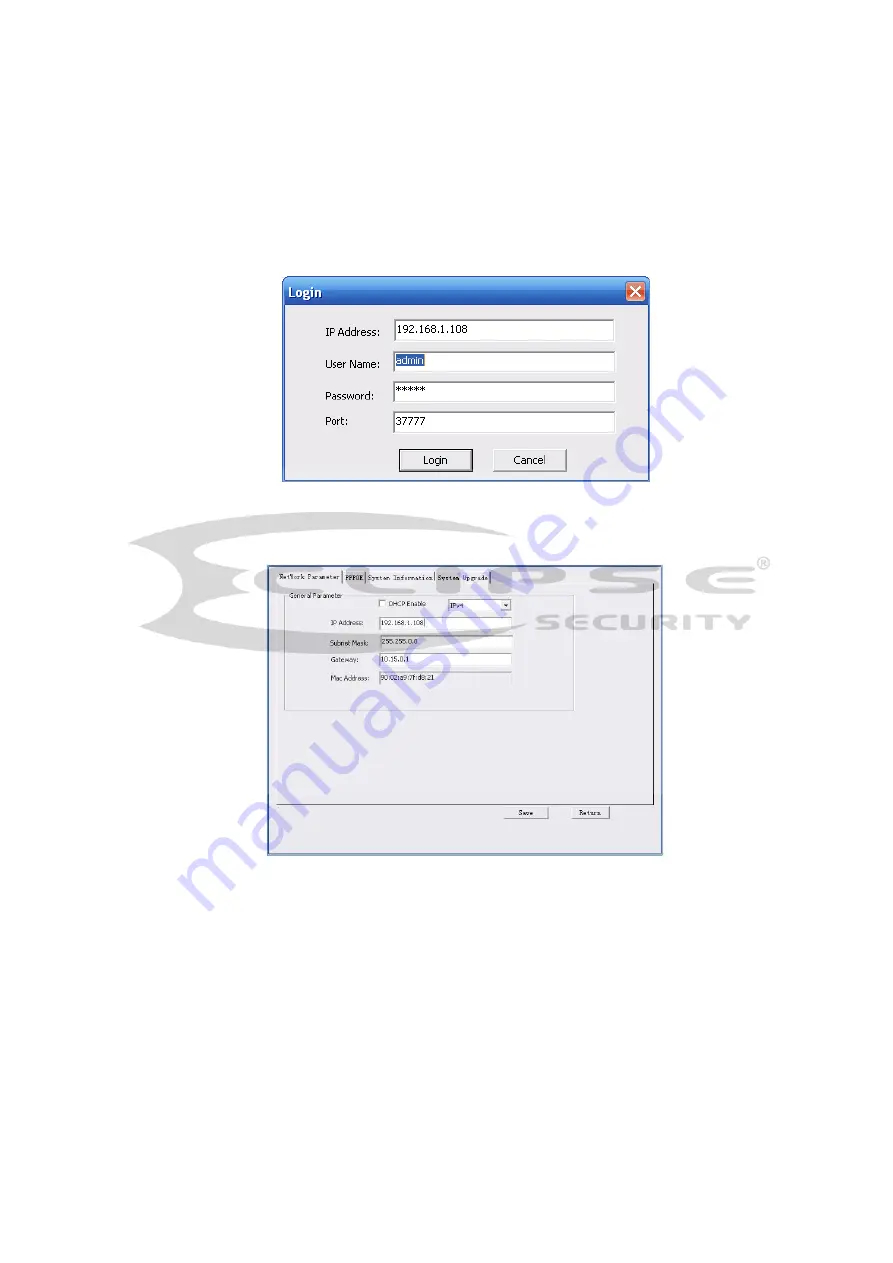
In the configuration tool search interface (Figure 4-1), please select a device IP address and then 

double click it to open the login interface. Or you can select an IP address and then click the Login 

button to go to the login interface. See Figure 4-3. 

In Figure 4-3, you can view device IP address, user name, password and port. Please modify the 

corresponding information to login.  

Please note the port information here shall be identical with the port value you set in TCP port in Web 

Network interface. Otherwise, you cannot login the device.  

If you are using device background upgrade port 3800 to login, other setups are all invalid. 


Figure 4-3 Login prompt 

After you logged in, the configuration tool main interface is shown as below. See Figure 4-4. 


Figure 4-4 Main interface 

For detailed information and operation instruction of the quick configuration tool, please refer 

to the


Quick Configuration Tool User’s Manual

 included in the resources CD. 

Summary of Contents for ECL-IP3B100V

Page 1: ...ECL IP3B100V User s Manual Version 1 1 0...

Page 2: ...r network camera This user s manual is designed to be a reference tool for your system Please read the following safeguard and warnings carefully before you use this series product Please keep this us...

Page 3: ...n Please install the proper power cut off device during the installation connection Always follow the instruction guide the manufacturer recommended 4 Qualified engineers needed All the examination an...

Page 4: ...nclosure when you are installing the device or clean the enclosure when you are doing maintenance work Please use professional optical clean method to clean the enclosure Improper enclosure clean meth...

Page 5: ...ction Combination Cable 8 2 2 Framework and Dimension 9 2 3 Bidirectional talk 10 2 3 1 Device end to PC end 10 2 3 2 PC end to the device end 10 2 4 Alarm Setup 10 3 Device Installation 12 3 1 Device...

Page 6: ...v 4 2 Operation 17 5 Web Operation 19 5 1 Network Connection 19 5 2 Login and Main Interface 19 6 FAQ 21 Appendix Toxic or Hazardous Materials or Elements 22...

Page 7: ...s User Management Different user rights for each group one user belongs to one group The user right shall not exceed the group right Storage Function Support central server backup function in accordan...

Page 8: ...terface such as WEB DSS PSS System Status Micro SD card status bit stream statistics log and software version Video Parameter Image Sensor 1 3 0 inch CMOS 1 2 9 inch CCD Pixel 1280 H 960 V 1920 H 1080...

Page 9: ...on and etc Alarm Input 2 channel input 1 channel output Record and Backup Record Priority Manual External alarm Video detect Schedule Local Storage Support Micro SD card hot swap Storage Management Su...

Page 10: ...ser customize Video Compression Standard H 264 H 264H MJPEG Video Frame Rate PAL Main stream 3M 20fps extra stream D1 20fps CIF 20fps Main stream 1080P 25fps extra stream D1 25fps CIF 25fps NTSC Main...

Page 11: ...DP RTCP SMTP FTP DHCP DNS DDNS PPPOE UPNP NTP Bonjour SNMP QoS IEEE802 Syslog Remote Operation Monitor system setup file download log information maintenance upgrade and etc AUX Interfa ce Video Outpu...

Page 12: ...Bit Rate H 264 32 8192Kbps adjustable MJPEG adjustable and bit rate is adjustable Support customized setup Video Flip Support mirror and flip function Snapshot Max 1f s snapshot File extension name i...

Page 13: ...log Remote Operation Monitor system setup file download log information maintenance upgrade and etc AUX Interfa ce Video Output 1 channel analog video output BNC port Reset Reset button General Parame...

Page 14: ...actual device label 2 RESET Reset button The reset button is to restore device factory default setup Press 3 5 seconds 3 I O I O cable port Includes alarm input and output 4 LAN Network port Ethernet...

Page 15: ...3 ALARM_IN1 Alarm input port 1 It is to receive the on off signal from the external alarm source 4 ALARM_IN2 Alarm input port 2 It is to receive the on off signal from the external alarm source 5 GND...

Page 16: ...er you enabled the audio talk function Click Talk button again to stop the bidirectional talk function Please note the on site listening operation is null during the bidirectional talk process Listeni...

Page 17: ...vice collects the logic 1 When the input signal is grounded the device collects the logic 0 Figure 2 5 Alarm input Please refer to the following figure for alarm output information See Figure 2 6 Port...

Page 18: ...ace Put the three fixed screws to the three holes of the bracket and then secure firmly Finally you can fix the bracket in the wall or surface Figure 3 1 Device installation illustration 3 2 Install M...

Page 19: ...od adjusts focus while rear rod adjusts zoom After adjusting rod rotate lens cover clockwise to fasten it See Figure 2 3 Note If you cannot rotate lens cover you can take down sunshield first Please p...

Page 20: ...the screw with inner hex wrench in accessories bag Rotate rear cover 360 horizontally and 90 vertically Rotate pedestal 360 Secure the screw with inner hex wrench after adjustment See Figure 2 4 Note...

Page 21: ...Button You can switch button to up down to zoom in out You also can switch button to left right to focus Long press button for 2s for auto focus which makes video clear See Figure 2 5 and 2 6 Note The...

Page 22: ...16 Figure 3 5 Button Position Figure 3 6 Button...

Page 23: ...n as in Figure 4 1 In the device list interface you can view device IP address port number subnet mask default gateway MAC address and etc Figure 4 1 Search interface Select one IP address and then ri...

Page 24: ...o login Please note the port information here shall be identical with the port value you set in TCP port in Web Network interface Otherwise you cannot login the device If you are using device backgrou...

Page 25: ...the PC and the network camera respectively Network camera default IP address is 192 168 1 108 Subnet mask is 255 255 255 0 Gateway is 192 168 1 1 Use order ping network camera address to check connect...

Page 26: ...gin After you successfully logged in please install WEB plug in unit Please refer to the Web Operation Manual included in the resource CD for detailed operation instruction See Figure 5 3 Figure 5 3 W...

Page 27: ...high speed card Audio function Please use active device for the audio monitor input otherwise there is no audio in the client end To guarantee setup update After you modified the important setup pleas...

Page 28: ...P period the toxic or hazardous substance or elements contained in products will not leak or mutate so that the use of these substances or elements will not result in any severe environmental pollutio...

Reviews: