background image

USER MANUAL /  MANUAL DE USUARIO 

– MICROSTAR 


Page 

27

 of 

64


INMANUUML019 USER MANUAL - M. USO OM-200 V.2023.01 ENG-ESP US 

7.2 ELECTRICAL CONNECTIONS 

Check the condition of all components and their aging process. 

Search for: 

  Faulty, broken or cut cables. 

  Faulty connection between the cable and the plug. 

  Oxide corrosion in connections pins. 


7.3 FUSE CHANGE 


Disconnect the power cord from the electrical network. 

1)  Disconnect the power cord from the electrical network 
2)  Remove the forearm access cover to reach the fuse housing. 


3)  Under de power cord connector there is a small rectangular plastic holder where the fuses 

are located. With the help of a screwdriver and with slight pressure, remove the lid. 

Summary of Contents for MICROSTAR Series

Page 1: ...thods without previous written authorization from ECLERIS Neither can it be reproduced multiplied or published through any electronic data processing form The information contained in this manual may...

Page 2: ...M INSTALLATION 12 4 5 BINOCULAR SPLITTER INSTALLATION 13 4 6 VIDEO CABLES INSTALLATION 15 5 OPERATION FUNCTIONS 16 5 1 MICROSCOPE OPERATION 16 5 2 CONNECTIONS 17 5 2 1 FOREARM 17 5 2 2 ARM 17 5 3 LIGH...

Page 3: ...SO OM 200 V 2023 01 ENG ESP US 7 1 1 CLEANING THE EXTERNAL SURFACES 26 7 1 2 DISINFECTION 26 7 1 3 CLEANING OF OBJECTIVE LENS AND EYEPIECES 26 7 2 ELECTRICAL CONNECTIONS 27 7 3 FUSE CHANGE 27 8 TECHNI...

Page 4: ...tective earth Ground Video output Equipotential bonding Freeze image function Manufacturer identification Name Address Video camera Serial number White balance function Manufacturing date MM AAAA Ligh...

Page 5: ...tion including a grounding in compliance with the regulations The microscope should be connected to the mains through the supplied cord or a replacement with the same certifications The mains should b...

Page 6: ...of electrical and electronic device 3 DESCRIPTION 3 1 INTENDED USE The microscope has been designed to perform observation in diagnostic and surgical procedures It is used in different medical specia...

Page 7: ...ion Binocular rotation Pantographic arm length OM 200F Floor stand Straight 23 03 585mm 45 Inclined 32 09 815mm 180 Inclinable 3 3 1 FLOOR STAND MICROSCOPE OM 200F Components 1 Optical Head 2 HD beam...

Page 8: ...OM 200 V 2023 01 ENG ESP US 10 Progressive brake 11 Progressive brake 12 Column 13 Microscope Base 3 3 2 OPTICAL HEAD 1 Magnification selector 2 Micro focus adjustment 3 Light filter selector 4 Diaph...

Page 9: ...ing the bolt into the ends of the base as indicated in the following figure A wrench should be used to tighten the wheel bolts solidly to the base of the microscope The base has 4 removable weights th...

Page 10: ...NUAL M USO OM 200 V 2023 01 ENG ESP US 4 2 COLUMN INSTALLATION Once the wheels and the base cover are placed the column must be mounted on the base Put the column in the central axis of the base as in...

Page 11: ...M 200 V 2023 01 ENG ESP US The column has to be mounted in the right position as indicated in the following figure Column Top Column Bottom 4 3 FOREARM COLUMN INSTALLATION Place the forearm on top of...

Page 12: ...M USO OM 200 V 2023 01 ENG ESP US 4 4 OPTICAL HEAD ARM INSTALLATION The optical head is mounted to the arm through a joint elbow of 60 as shown in the picture below Embellishing screw E Tensor screw D...

Page 13: ...urn Place the tensor screw D and adjusted to the maximum using a corresponding Allen key as the following picture Then place the embellishing screw E on top and adjust it completely Finally adjust the...

Page 14: ...hat the binocular is inserted centrally in the upper part of the head After the joint is centered and flat against the Optical head press the adjustment screw so that the binocular remains firmly atta...

Page 15: ...of the power cables is slightly longer this one must be connected to the lighting system Once the HDMI cable is connected it should be secured by the adjustment screws in order to avoid damage of the...

Page 16: ...1 Connect the power supply cable to the microscope and then to the mains 2 Press the power switch on the forearm to turn the unit on the green indicator light will turn on The light source turns on a...

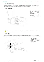
Page 17: ...o access the connectors 5 2 1 FOREARM 1 100 VA auxiliary power output monitor connection 2 Power cord connector 100 240 V 3 HDMI output monitor connection The power consumption of the auxiliary power...

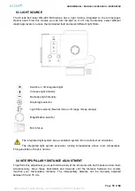
Page 18: ...ase light intensity Diaphragm selector Light filter selector Neutral Green Orange Deep orange Magnification selector Micro focus The integrated light system has a ventilation system Do not obstruct ai...

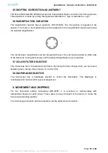
Page 19: ...ification can be changed with any of the commands located on either side of the binocular turning them slowly until the desired magnification level is reached 5 7 COLOR FILTER SELECTOR The microscope...

Page 20: ...tioning of the microscope will be achieved by the articulated arm It has been designed and calibrated to achieve auto stability in the desired position with a minimum effort The Pantographic arm has a...

Page 21: ...HEAD The microscope has an elbow that positions the optical head at a fixed angle in relation to the arm Movement can be regulated or totally blocked using the adjustment control command If this comm...

Page 22: ...is 0 360 degrees The movement can be adjusted or completely locked using the control knob 6 5 OPTICAL HEAD TILT The microscope allows 150 tilt and has an adjustment knob on the head s right hand side...

Page 23: ...f the microscope Set the brakes to avoid movements of the forearm arm and Optical head Disconnect the power supply cable from the electrical network and tie it firmly to the microscope s column Loosen...

Page 24: ...f 64 INMANUUML019 USER MANUAL M USO OM 200 V 2023 01 ENG ESP US 3 Mount the monitor holder on the back of the monitor and place the 4 Allen screws 4 Place the column support to the end of the monitor...

Page 25: ...USER MANUAL MANUAL DE USUARIO MICROSTAR Page 25 of 64 INMANUUML019 USER MANUAL M USO OM 200 V 2023 01 ENG ESP US...

Page 26: ...supply cable from the mains 7 1 1 CLEANING THE EXTERNAL SURFACES Clean the external surface of the device using a piece of cotton or cloth moistened with mild detergent or soap Use only adequate produ...

Page 27: ...ulty connection between the cable and the plug Oxide corrosion in connections pins 7 3 FUSE CHANGE Disconnect the power cord from the electrical network 1 Disconnect the power cord from the electrical...

Page 28: ...SYSTEM Composed of apochromatic lenses with a fungus resistant coating BINOCULAR TUBES 45 inclined straight 180 inclinable OBJECTIVE LENS f 200 250 300 400 mm one included MAGNIFICATIONS Apochromatic...

Page 29: ...urs approx REFRIGERATION Forced DIMMER Electronic PANTOGRAPH ARM TYPE WBS Weight Balance System ROTATION MOVEMENTS Proximal and distal rolling bearings system CONNECTIONS DC Plug 12Vcc 4 Acc connectio...

Page 30: ...DE USUARIO MICROSTAR Page 30 of 64 INMANUUML019 USER MANUAL M USO OM 200 V 2023 01 ENG ESP US STORAGE AND TRANSPORTATION CONDITIONS TEMPERATURE 30 50 C HUMIDITY 10 95 relative humidity ATMOSPHERIC PRE...

Page 31: ...cal head Change the power cord Change the plug Change the fuse Change the position to a lower height The light intensity is incorrect The light intensity has not been set correctly Adjust the light in...

Page 32: ...is not damaged during transportation ECLERIS shall not be liable for damages that may occur during transportation caused by deficient packaging 11 WARRANTY ECLERIS states that the ECLERIS Microstar OM...

Page 33: ...ec nico o de otra manera se proh be sin el consentimiento escrito anterior del due o de derechos reservados La informaci n contenida en este manual puede ser modificada o ampliada sin notificaci n pre...

Page 34: ...TALACION DEL BINOCULAR SISTEMA DE VIDEO 45 4 6 INSTALACION CABLES DE VIDEO 47 5 OPERACI N FUNCIONES 48 5 1 OPERACI N DEL MICROSCOPIO 48 5 2 CONEXIONES 49 5 2 1 ANTEBRAZO 49 5 2 2 BRAZO 49 5 3 FUENTE D...

Page 35: ...OM 200 V 2023 01 ENG ESP US 7 1 1 LIMPIEZA DE SUPERFICIES EXTERIORES 58 7 1 2 DESINFECCI N 58 7 1 3 LIMPIEZA DE OBJETIVOS Y OCULARES 58 7 2 CONEXIONES EL CTRICAS 58 7 3 CAMBIO DE FUSIBLE 59 8 ESPECIF...

Page 36: ...e Protecci n Salida de Video Tierra de Equipotencialidad Congelar Imagen Identificaci n del fabricante Nombre Direcci n C mara de Video N mero de serie Balance de Blancos Fecha de fabricaci n MM AAAA...

Page 37: ...entaci n con tierra de protecci n No instale el equipo pr ximo a fuentes de calor tales como estufas El Microscopio debe ser empleado en locales cuya instalaci n el ctrica posea puesta a tierra que cu...

Page 38: ...ento del equipo Reparaci n o manipulaci n por personal no autorizado se produjeran da os personales o materiales a terceros ECLERIS el fabricante y vendedor de estos equipos no asumen responsabilidad...

Page 39: ...ble especial que contiene 1 ficha HDMI macho para conectar al sistema de video y 2 fichas de alimentaci n DC PLUG para alimentar el sistema de video y la luz integrada 3 3 1 MICROSCOPIO CON ESTATIVO D...

Page 40: ...ANUUML019 USER MANUAL M USO OM 200 V 2023 01 ENG ESP US 3 3 2 CABEZAL 1 Selector de Magnificador 2 Ajuste micro enfoque 3 Selector de Filtro de Luz 4 Selector de Diafragma 5 Encendido Apagado Luz 6 In...

Page 41: ...contrapesos Las ruedas se montan enroscando el perno de la misma en los extremos de la base como indica la figura siguiente Se debe utilizar una llave fija para ajustar los pernos de la rueda s lidam...

Page 42: ...rtor pl stico sobre la base de la columna como indica la siguiente figura 4 2 INSTALACION DE LA COLUMNA La columna se debe instalar sobre la base una vez que est n las ruedas y el cobertor colocados P...

Page 43: ...en la posici n correcta respetando la parte superior e inferior de la columna como se indica en la siguiente figura Columna Parte Superior Columna Parte Inferior 4 3 INSTALACION DEL ANTEBRAZO A LA CO...

Page 44: ...CROSTAR P gina 44 de 64 INMANUUML019 USER MANUAL M USO OM 200 V 2023 01 ENG ESP US 4 4 INSTALACION DEL CABEZAL A BRAZO El cabezal est montado al brazo mediante un codo de articulaci n de 60 como se in...

Page 45: ...r D y aj stelo a su m ximo utilizando una llave Allen correspondiente seg n la imagen a la izquierda Coloque el tornillo embellecedor E y aj stelo completamente Finalmente ajustara el tornillo de segu...

Page 46: ...forma centrada en la parte superior del cabezal Luego de que el encastre sea centrado y plano contra el cabezal oprima el tornillo de ajuste para que el binocular permanezca solidariamente vinculado a...

Page 47: ...ables de alimentaci n es levemente m s largo este cable debe ser conectado al sistema de luz para mantener la tensi n de los cables al m nimo Una vez conectado el cable HDMI deber fijarse mediante tor...

Page 48: ...el cable de alimentaci n al microscopio y luego a la red el ctrica 2 Encienda la unidad presionando el interruptor de encendido que se encuentra en el antebrazo se encender el indicador luminoso verde...

Page 49: ...or debe retirarse la tapa del antebrazo 5 2 1 ANTEBRAZO 1 Salida auxiliar de alimentaci n de 100 VA conexi n a monitor 2 Conector del cable de alimentaci n del equipo 100 240 V 3 Salida HDMI conexi n...

Page 50: ...grada en el cabezal Aumento del nivel de intensidad luminosa Disminuci n del nivel de intensidad luminosa Selector de Diafragma Selector de Filtro de Luz Neutro Verde Naranja Naranja Intenso Selector...

Page 51: ...i n seleccionada Puede cambiarse la magnificaci n del microscopio con cualquiera de los comandos ubicados a ambos lados del binocular girando el comando suavemente hasta lograr el aumento deseado 5 7...

Page 52: ...en altura del microscopio el cual ha sido dise ado y calibrado para alcanzar la auto estabilidad en la posici n deseada con m nimo esfuerzo El brazo paralelogramo posee un sistema de auto compensaci...

Page 53: ...oscopio posee un codo que posiciona al cabezal a un ngulo fijo de 60 en relaci n al brazo y el cabezal puede rotar en ese eje 320 Se puede regular o completamente anular el movimiento utilizando su co...

Page 54: ...ado utilizando el comando de control 6 5 MOVIMIENTO DE BALANCEO DEL CABEZAL MOVIMIENTO BASCULANTE El microscopio permite una inclinaci n de 150 y posee un control de paro o comando de control ubicado...

Page 55: ...los frenos para evitar movimientos del antebrazo brazo cabezal Desconecte el cable de alimentaci n de la red el ctrica y suj telo a la columna del microscopio Libere los frenos de las ruedas Debido a...

Page 56: ...NUUML019 USER MANUAL M USO OM 200 V 2023 01 ENG ESP US 3 Monte en la parte trasera del monitor el soporte del monitor y coloque los 4 tornillos Allen 4 Inserte la columna soporte al extremo del soport...

Page 57: ...MANUAL DE USUARIO USER MANUAL MICROSTAR P gina 57 de 64 INMANUUML019 USER MANUAL M USO OM 200 V 2023 01 ENG ESP US...

Page 58: ...ERIORES Limpie la superficie externa del equipo utilizando algod n o un pa o humedecido con detergente neutro o jab n neutro Utilice s lo productos adecuados para la limpieza de superficies externas d...

Page 59: ...IBLE Desconecte el cable de alimentaci n de la red el ctrica 1 Desconecte el cable de alimentaci n de la red el ctrica 2 Retire la tapa del antebrazo para acceder al alojamiento de los fusibles 3 Deba...

Page 60: ...SISTEMA OPTICO Compuesto por lentes apocrom ticas con capa protectora anti hongos TUBOS BINOCULARES 45 inclinado recto inclinable 180 LENTES OBJETIVOS f 200 250 300 400 mm uno incluido AUMENTOS Cambia...

Page 61: ...x VIDA UTIL DEL SISTEMA DE LEDS Aprox 50000 horas REFRIGERACION Forzada DIMMER Electr nico BRAZO PANTOGRAFICO TIPO Compensaci n de pesos WBS Weight Balance System MOVIMIENTOS DE ROTACION Sistema con c...

Page 62: ...ANUAL M USO OM 200 V 2023 01 ENG ESP US CONDICIONES DE SERVICIO TEMPERATURA 10 40 C HUMEDAD 35 75 humedad relativa PRESION ATMOSFERICA 700 1060 hPa CONDICIONES DE ALMACENAMIENTO Y TRANSPORTE TEMPERATU...

Page 63: ...tiladores no funcionan Obstrucci n de la circulaci n de aire Contacte al servicio t cnico No obstruir la circulaci n de aire Los fusibles se queman Consumo de potencia excesiva en la salida auxiliar d...

Page 64: ...ondiciones de uso adecuadas de acuerdo a las indicaciones presentadas en este manual El per odo de garant a es por el t rmino de un 1 a o a partir de la fecha de la factura de compra ECLERIS no es res...

Reviews: