background image


7

4.3. Indicators 


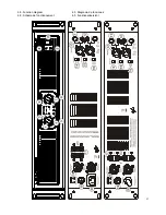
The LPA amplifiers provide a simple and effective system of indicators: 


• 

“PROTECT” indicators (2): They indicate the absence of a power signal in the loudspeaker output of the 
amplifier. They may be activated for various reasons: 

1.  In the startup period, from when the power-on button is pressed until the startup time necessary 

to stabilize the internal voltages of the amplifier has been completed (approximately 10 seconds). 

2.  Due to the presence of a short-circuit in the output terminals of the amplifier (crossed cable, 

damaged loudspeaker, etc.). 

3.  If the amplifier is supplying a continuous signal or a very low-frequency signal, which could 

damage the loudspeakers. 


CAUTION: If these indicators remain permanently switched on, even when all signal input and 
output cables have been disconnected from the amplifier, this could be a sign of a malfunction 
which should be analyzed by the official Ecler technical support service. 


• 

“CLIP” indicators (3): They light up when the amplified signal present in the amplifier output is just below 
the level of clipping or saturation. This system always provides a true indication, regardless of the 
variations in the mains voltage. When operating at high power levels, it is normal for the CLIP indicators 
to light up briefly at the moment of low frequencies, because it is the low frequencies which make the 
greatest energy contribution in the audible spectrum. You must try to ensure that these indicators do not 
remain lit up permanently in the normal operating conditions of the amplifier. 


• 

“SIGNAL” indicators (4): They indicate the presence of a signal in the amplifier inputs. These indicators 
light up when the signal present in the input exceeds the threshold of –40 dB. 


5. CLEANING 


The front panel should not be cleaned with dissolvent or abrasive substances because silk-printing 

could be damaged. To clean it, use a soft cloth slightly wet with water and neutral liquid soap; dry it with a clean 
cloth. Be careful that water never gets into the amplifier through the holes of the front panel. 

Summary of Contents for LPA10000

Page 1: ...USER MANUAL MANUAL DE INSTRUCCIONES NOTICE D EMPLOI BEDIENUNGSANLEITUNG ...

Page 2: ......

Page 3: ...rcuit 06 3 6 Output connections 06 4 OPERATION AND USAGE 06 4 1 Start up 06 4 2 Input attenuators 06 4 3 Indicators 07 5 CLEANING 07 6 DIAGRAMS 23 6 1 Connection diagram 23 6 2 Technical characteristics 24 6 3 Block diagram 25 6 4 Function list 26 6 5 Function diagram 27 All numbers subject to variation due to production tolerances ECLER S A reserves the right to make changes or improvements in ma...

Page 4: ...ls are 2 rack units high and are based on a robust chassis Thanks to their oversize power supply the amplifiers can work comfortably at loads of 4 Ω The LPAs include balanced inputs via XLR3 connectors and a jack and non balanced inputs via RCA connectors Their outputs offer complete versatility thanks to the dual format used connectors of the safety terminal type with a normalized distance and Sp...

Page 5: ...E THE FUSE WITH ANOTHER ONE WITH A HIGHER VALUE The mains cables must not be near the shielded cables carrying the audio signal as this could cause humming 3 3 Input signal connections The input connectors for the balanced signal are of the XLR 3 and JACK type 11 13 The assignment is as follows XLR 3 JACK Hot or direct signal Pin 2 Tip Cold or phase inverted signal Pin 3 Ring Ground Pin 1 Sleeve F...

Page 6: ...connected to the amplifier operating in BRIDGE mode is not lower than 8Ω ATTENTION Terminals 1 and 1 should only be used in case of STEREO or PARALLEL mode and terminals 2 and 2 in BRIDGED mode Any other combination may impair final audio quality The connection cable that joins the amplifiers outputs and the loudspeakers must be of good quality sufficient section and as short as possible This is m...

Page 7: ...cal support service CLIP indicators 3 They light up when the amplified signal present in the amplifier output is just below the level of clipping or saturation This system always provides a true indication regardless of the variations in the mains voltage When operating at high power levels it is normal for the CLIP indicators to light up briefly at the moment of low frequencies because it is the ...

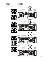
Page 8: ...23 6 DIAGRAMS 6 DIAGRAMAS 6 SCHÉMAS 6 DIAGRAMME 6 1 Connection diagram 6 1 Diagrama de conexión 6 1 Schéma de connexion 6 1 Anschlußdiagramm ...

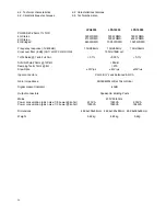
Page 9: ...filter 3dB CH1 LOW CH2 HIGH 150Hz 18dB oct THD Noise 1kHz Full Pwr 0 1 0 05 0 1 S N N 20Hz 20kHz 1W 4Ω 85dB Damping factor 1kHz 8Ω 270 Slew Rate 37V µs 43V µs 30V µs Input connectors XLR3 Jack balanced RCA Gain Impedance 26 32dB 20kΩ Bal 10kΩ Unbal Signal present indicator 40dB Output connectors Speakon Binding Posts Mains 230V 50 60Hz Power consumption pink noise 1 8 power 4ohm 670VA 1040VA 600VA...

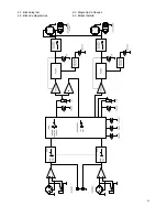
Page 10: ...25 6 3 Block diagram 6 3 Diagrama de bloques 6 3 Blocs de diagrammes 6 3 Blockschatbild ...

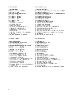
Page 11: ...avoces 19 Fuse holder 19 Portafusible 20 Mains socket except LPA16000 20 Base de red excepto LPA16000 6 4 Liste de fonctions 6 4 Funktionsliste 1 Atténuateurs d entrée 1 Eingangsregler 2 Indicateur de protection PROTECT 2 Schutzanzeige PROTECT 3 Voyant d écrêtage CLIP 3 Clip Anzeige CLIP 4 Indicateur de présence du signal SIGNAL 4 Signalanzeige SIGNAL 5 Indicateur lumineux PARAL 5 Kontroll LED PAR...

Page 12: ...27 6 5 Function diagram 6 5 Diagrama de funciones 6 5 Schéma de fonctionnement 6 5 Funktionsübersicht ...

Page 13: ...ECLER Laboratorio de electro acústica S A Motors 166 168 08038 Barcelona Spain INTERNET http www ecler com E mail info ecler es 50 0228 01 00 ...

Reviews: