background image

11

Before you start

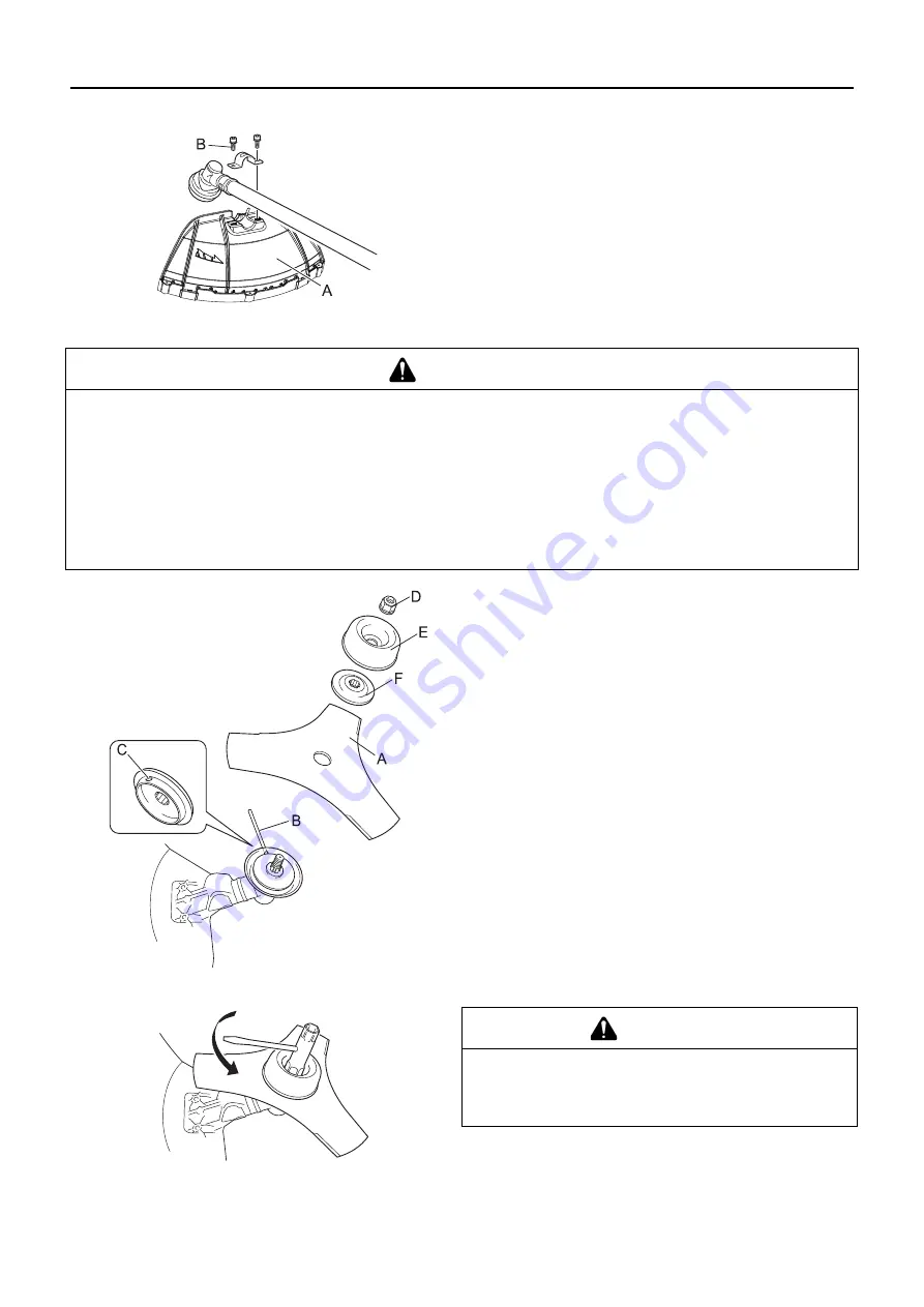
Installation of shield

1.  Fit shield (A) to mounting portion of angle transmission and 

tighten 2 bolts (B).

Installing blade (option)

1.  Inspect blades (A) before installation. Check for sharpness. 

Dull blades increase the risk of blade kickback reactions. 
Small cracks can develop into fractures resulting in a piece 
of blade flying off during operation. Discard cracked blades 
no matter how small the crack.

2.  Insert locking tool (B) into a hole located on the right side of 

angle transmission while forcing retainer spring to the left 
side.

3.  Insert locking tool further into blade retainer fixing slot (C) to 

fix output shaft.

4.  Using the socket wrench, remove the nut (D), cup (E), and 

lower blade retainer (F).

5.  Securely tighten the blade, lower blade retainer, cup, and nut 

by hand.

6.  Tighten the nut (turn anticlockwise) using a socket wrench. 

Never fasten while applying your weight. Otherwise the 
thread of nut could be broken.

7.  Remove locking tool.

 WARNING

Wear heavy duty gloves when working with the trimmer blade.

When replacing the trimmer blade during a trimming task, ensure that the engine is switched off and that the blades 
have stopped.

When turning the product over to replace the trimmer blade, ensure that the fuel tank cap is securely in place.

Do not attempt to fit the trimmer blade with one hand or without using the socket spanner. Fit the trimmer blade ac-
curately using the supplied socket spanner and tighten firmly in position.

Do not use any tools other than the provided socket spanner to tighten the blade; a pneumatic or electric tool may 
tighten the blade more than necessary and cause the nut or the output shaft to break.

If worn nut and cup for blade are used, there is a danger of blade getting loose. Replace them with new one.

Failure to do so could lead to an injury or serious accident, or cause a fire.

 CAUTION

Fix output shaft securely using locking tool in order to 
prevent it form rotating when blade is mounted. Other-
wise, the blade fastening nut will not be tightened suffi-
ciently.

Summary of Contents for SRM-4510

Page 1: ...1Cover ENGLISH OPERATOR S MANUAL GRASS TRIMMER BRUSHCUTTER SRM 4510 WARNING READ THE INSTRUCTIONS CAREFULLY AND FOLLOW THE RULES FOR SAFE OPERATION FAILURE TO DO SO COULD RESULT IN SERIOUS INJURY EN...

Page 2: ...12 Preparing the fuel 12 Engine operation 14 Starting the engine 14 Stopping the engine 15 Trimming operation 16 Using shoulder harness 17 Basic trimming operation with nylon line cutting head 17 Bas...

Page 3: ...the product You must not modify the product To do so could lead to an accident or serious injury Any malfunction resulting from a modification to the product will not be covered by the manufacturer s...

Page 4: ...the repetitive movement Do exercises to strengthen hand and arm muscles See a doctor if you feel tingling numbness or pain in your fingers hands wrists or arms The sooner RSI is diag nosed the more l...

Page 5: ...fire or smoke If fire comes from the engine or smoke appears from any area other than the exhaust vent first distance yourself from the product to ensure your physical safety Use a shovel to throw sa...

Page 6: ...protection and gloves Petrol and oil mixture Emergency stop Choke Control Cold Start Position Choke Closed Warning Thrown objects Choke Control Run Position Choke Open Warning side thrust Carburettor...

Page 7: ...tand what the decal means before using your product If the decal becomes unreadable due to wear and tear or damage or peels off and is lost please purchase a replacement decal from your dealer and att...

Page 8: ...ked 7 Ignition switch Slide switch mounted on top of the throttle trigger housing move switch forward to RUN backward to STOP position 8 Throttle trigger Activated by the operator s finger for control...

Page 9: ...ng or broken Engine Operation Shaft Handle 1 Throttle lever 2 Engine 3 Operator s manual 4 Safety goggles 5 Caution tag 6 Shaft tube 7 Locking tool 8 Socket wrench 9 L wrenches 10 Spanner 11 Bolts 12...

Page 10: ...the slot D for rotation prevention 3 Locate the throttle grip so that the screw can pass through the stopper hole E 4 Securely tighten the screw and nut 1 Loosen handle bar support bolts A 2 Locate ha...

Page 11: ...ut could be broken 7 Remove locking tool WARNING Wear heavy duty gloves when working with the trimmer blade When replacing the trimmer blade during a trimming task ensure that the engine is switched o...

Page 12: ...Balancing and levelling as above may require relocation of the clamp and readjustment of the harness straps Also each type of cutting attachment and shield mounted on the unit may require balancing Pr...

Page 13: ...e Always loosen fuel caps slowly allowing pressure to equalize Otherwise fuel may get spewed Mop up any fuel that overflows or spills out due to overfilling Fuel spills can cause fire and burns when i...

Page 14: ...if there are abnormal vibrations or sounds Contact your dealer to have it repaired Accidents involving parts that fall or shatter off can cause wounds or serious injury The exhaust fumes from the eng...

Page 15: ...m engine 1 Move the ignition switch A to the Start position 2 Make sure that the throttle trigger D is at the idle speed po sition 3 Check that the choke lever is in the Run position 4 If no fuel is v...

Page 16: ...gn objects ricochet off the cutting attachment or wire and other materials twisted round the product spring off it In the following situations turn off the engine immediately and ensure that the cutti...

Page 17: ...feed only up to the wire If you go too far the line will snap off around the wire Trimming can be done to cut through weed stems one at a time Place the nylon line cutting head near the bottom of the...

Page 18: ...the shield See appropriate pic ture This results in the debris being thrown away from you Tilting the head to the wrong side will shoot the debris toward you If the nylon line cutting head is held fla...

Page 19: ...rp Dull blades increase the chance of kick out and injury to yourself and bystanders Plastic Nylon Grass Weed Blades may be used where ever the nylon line head is used Do not use this blade for heavy...

Page 20: ...arts and consumables please use only genuine parts and designated products and components Using parts from other manufacturers or non designated components may result in a malfunction Area Maintenance...

Page 21: ...allow it to idle 2 3 minutes until warm 2 If the attachment moves when the engine is at idle reduce the idle speed by turning the idle adjustment screw T coun ter clockwise 3 Repeat the process of acc...

Page 22: ...equest your dealer to inspect or replace NOTE When the carburettor cannot be adjusted properly with the idle speed adjustment screw T you must contact an authorized service dealer IMPORTANT To maintai...

Page 23: ...kgf cm to 170 kgf cm The spark test for checking whether the spark plug is spark ing must be carried out by your dealer Angle transmission 1 Remove the plug A and drain screw B from the angle transmis...

Page 24: ...k plug is dirty or damp 1 Fuel degradation 2 Incorrect electrode gap 3 Carbon deposits 4 Electrical fault 1 Replace 2 Adjust or replace 3 Clean or replace 4 Consult your dealer Engine starts but no ac...

Page 25: ...te quantity around 10 mL of clean new 2 stroke engine oil to the cyl inder via the spark plug hole 9 Place a piece of clean cloth over the spark plug hole 10 Pull 2 or 3 times on the starter grip to d...

Page 26: ...1 part 2 Cutting attachment option Blade centre hole diameter Thread 25 4 mm Left handed thread M12 1 75 pitch Gear Case Gear ratio and lubrication Rotational direction of output shaft viewed from ab...

Page 27: ...27 1Notes and rear cover MEMORANDUM...

Page 28: ...X750226 7100 2019 1 7 2 Suehirocho Ohme Tokyo 198 8760 JAPAN PHONE 81 428 32 6118 FAX 81 428 32 6145...

Reviews: