26
EXHAUST
SYSTEM
Spark Arrestor Screen
Level 2.
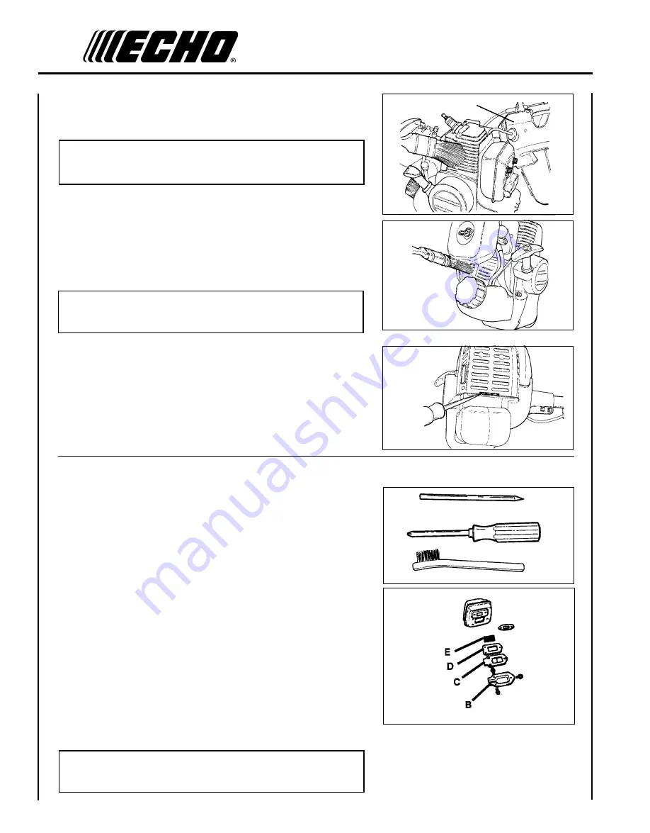
Tools required: Cross-head screwdriver, soft metal brush, wooden
carbon scraper.
Parts Required: Screen P/N 14586240630, Gasket Lid P/N 14586642031
1. Remove engine cover (A). See “Cleaning Cooling System” pages
25 & 26 for step by step instructions.
2. Place piston at Top Dead Center (TDC) to prevent carbon/dirt from
entering cylinder.
3. Remove spark arrestor screen cover (B), screen holder (C), gasket
(D) and screen (E) from muffler body.
4. Clean carbon deposits from screen and muffler components.
5. Replace screen if it is cracked, plugged or has holes burned
through.
6. Assemble components in reverse order.
NOTE
When installing the engine cover, be certain the tab of the metal
deflector shield is in the slot of the engine cover.
2. Remove the four screws that retain the engine cover (A). Two at
the top of the starter, two on either side of the front. Lift the cover
from the engine and lay to the front of the trimmer.
NOTE
The throttle linkage remains assembled to the cover and the spark
plug lead and grommet remain installed.
3. Use the wooden stick or brush to remove dirt form cylinder fins.
4. Remove grass and leaves from the grid between the recoil starter
and fuel tank.
5. Assemble components in reverse order.
NOTE
When installing the cover, be certain the tab of the metal deflector
shield is in the slot of the engine cover.
A
Summary of Contents for SRM-2100 - PARTS CATALOG SERIAL NUMBER 001001 THRU 159490
Page 2: ......
Page 33: ...GRASS TRIMMER BRUSH CUTTER OPERATOR S MANUAL 33 NOTES ...
Page 34: ...34 NOTES ...
Page 35: ...GRASS TRIMMER BRUSH CUTTER OPERATOR S MANUAL 35 NOTES ...


