background image

3

P

OWER

 B

LOWER

O

PERATOR

'

S

 M

ANUAL

S

AFETY

DECALS

Locate these safety decals on your unit.   Make sure the decals are
legible and that you understand and follow the instructions on them.
If a decal cannot be read, a new one can be ordered from your ECHO
dealer.  See PARTS ORDERING instructions for specific information.

IMPORTANT

NOTE

M

ANUAL

 S

AFETY

 S

YMBOLS


AND

 I

MPORTANT

 I

NFORMATION

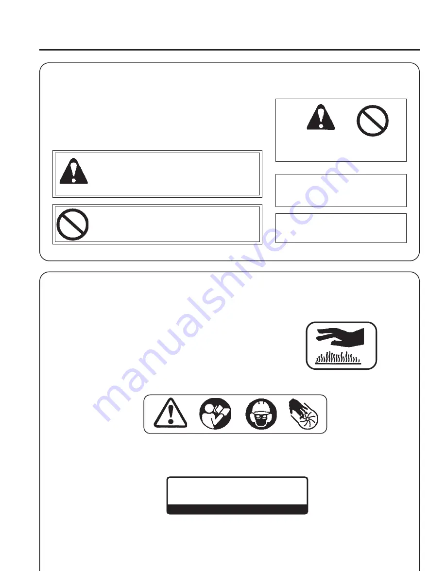
Throughout this manual and on the product itself, you will find safety
alerts and helpful, informational messages preceded by symbols or key
words.  The following is an explanation of those symbols and key
words and what they mean to you.

This symbol accompanied by the words WARNING and
DANGER calls attention to an act or condition that can lead
to serious personal injury to operator and bystanders.

The circle with the slash symbol means whatever is shown
within the circle is prohibited.

IMPORTANT  The enclosed message provides
information necessary for the protection of the
unit.

NOTE  This enclosed message provides tips for
use, care and maintenance of the unit.

Hot Decal (near muffler)

General Warning Decal (located on top of blower)

P/N 89016006361

P/N 89016009461

73

   Category III

dB(A)

Measured at 50 ft. (15m) per ANSI B175.2

P/N X508000160

Sound Label (located on blower housing)

Summary of Contents for PB-602

Page 1: ...MODEL PB 602 Serial Number 03001001 03999999 WARNING DANGER Readrulesforsafeoperationandallinstructionscarefully ECHOprovidesthisOperator s Manualwhichmustbereadandunderstoodforproperandsafeoperation...

Page 2: ...Service 24 ECHO Consumer Product Support 24 Warranty Card 24 Additional or Replacement Manuals 24 Specifications descriptions and illustrative material in this literature are as accurate as known at t...

Page 3: ...lowing is an explanation of those symbols and key words and what they mean to you This symbol accompanied by the words WARNING and DANGER calls attention to an act or condition that can lead to seriou...

Page 4: ...used Proper Clothing Wear snug fitting durable clothing Pants should have long legs shirts with long sleeves DONOTWEARSHORTS DONOTWEARTIES SCARVES JEWELRY Wear sturdy work shoes with nonskid soles DON...

Page 5: ...ation and cold Exposure to vibration and cold may cause tingling and burning sensations followed by loss of color and numbness in the fingers The following precautions are strongly recommended because...

Page 6: ...le emissions regulations provided that approved maintenance procedures are followed as listed in the Maintenance Section of this manual DetermineOperationArea Review area to be cleared Look for potent...

Page 7: ...___ 1 Operator s Manual ___ 1 Warranty Registration Card ___ 1 ECHO Emissions and Warranty Statement ___ 1 PlasticBag ___ 2 Clamps w screws ___ 1 StickHandle ___ 1 Bolt6x45 ___ 1 Washer 6 ___ 1 Wing...

Page 8: ...e starting engine draws fresh fuel from the fuel tank priming the carburetor for starting Pump primer bulb until fuel is visible and flows freely in the clear fuel tank return line Pump bulb an additi...

Page 9: ...M 7YGap0 65mm 0 026in ExhaustSystem SparkArrestorMuffler Fuel Mixed GasolineandTwo strokeOil Fuel OilRatio 50 1 two stroke air cooled engine oil Gasoline 89 Octane unleaded DO NOT use fuel containing...

Page 10: ...be used to ease assembly of flexible pipe to blowerelbow 4 Loosen wing nut E completely and expand stick handle clamp F 5 Align notches G in handle clamp with pipe pegs H Stick handle should be angled...

Page 11: ...Useextremecarewhenmixing storingor handling or serious personal injury may result Use an approved fuel container DONOTsmokenearfuel DO NOT allow flames or sparks near fuel Fuel tanks cans may be under...

Page 12: ...Move throttle lever A to START IDLE DETENT position 2 Choke Move choke B to Cold Start position 3 Primer Pump primer bulb C until fuel is visible and flows freely in the clear fuel tank return line P...

Page 13: ...Recoil Starter Pull recoil starter handle D and engine should start NOTE If engine does not start after 5 pulls use cold start procedures STOPPING ENGINE 1 Throttle Lever Move throttle lever A to idle...

Page 14: ...le for a few minutes 3 Set engine speed with throttle lever A 4 Use lower speed to blow dry grass and leaves from walks patios and drives 5 Additional speed may be necessary to clean leaves from a law...

Page 15: ...U O H 6 S H T N O M 0 7 2 R O S R U O H Y L R A E Y s e r u d e c o r P e c n a n e t n i a M r e l a e D o h c E d e d n e m m o c e R t r o P t s u a h x E r e d n i l y C n o b r a c e D n a e l C...

Page 16: ...mage If element is fuel soaked and very dirty replace 3 If element can be cleaned and reused be certain it still fits the cavity in the air cleaner cover is installed with the original side out FUEL F...

Page 17: ...d None if you are careful IMPORTANT To maintain proper engine operating temperatures cooling air must pass freely through the cylinder fin area This flow of air carries combustion heat away from the e...

Page 18: ...be checked periodically 1 Remove spark plug and engine cover five screws 2 Remove spark arrestor cover A gasket B and spark arrestor screen C frommuffler 3 Clean carbon deposits from muffler component...

Page 19: ...hesitate on acceleration For engine operation below 2 000 feet turn the high speed needle rich CCW until the engine runs between 7 000 and 8 000 RPM Then turn the low speed needle rich CCW until the...

Page 20: ...t which can cause engine failure Do not exceed recommended HI speed engine R P M during operation or for long periods during adjustment 1 Start engine run at idle for one minute 2 Complete warm up by...

Page 21: ...h t i w d e r e v o C l e u f h t i w d e l u o F e v i t c e f e d g u l P n i 6 2 0 0 m m 5 6 o t t s u j d A e c a l p e r r o n a e l C e c a l p e r r o n a e l C g u l p e c a l p e R s n u r e...

Page 22: ...t store your unit for a prolonged period of time 30 days or longer without performing protective storage mainte nance which includes the following 1 Store unit in a dry dust free place out of the reac...

Page 23: ...23 POWER BLOWER OPERATOR S MANUAL NOTES...

Page 24: ...now the model and serial number of your unit to help your Consumer Product Support Representative WARRANTY REGISTRATION You may register your Echo equipment using the warranty registration card or reg...

Reviews: