background image


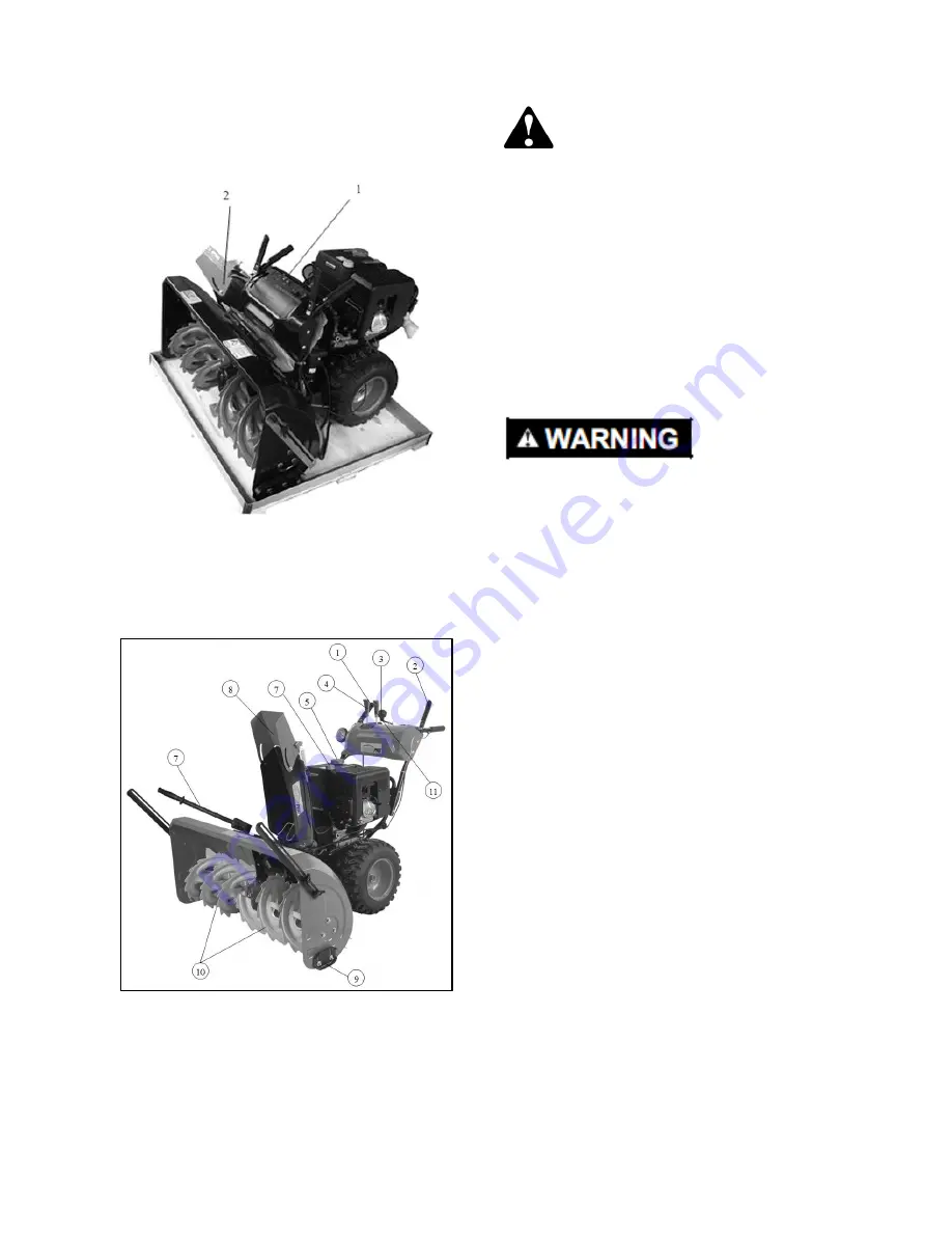
Package Contents 

1.  Armrest 
2.  Chute (attached with instructions and fittings) 


Controls & Features 


1. 

Drive control 

7. Clean-out tool 

2. 

Auger control 

8. Dipstick 

3. 

Chute direction control 

9. Skid shoes 

4. 

Speed control 

10. Auger 

5. 

Gas cap 

11. Chute control 

6. 

Chute assembly 


Residual Risks 

Even when the machine is used as prescribed it is 
not possible to eliminate all residual risk factors. 
The  following  hazards  may  arise  in  connection 
with the machine’s construction and design: 

1. 

Damage  to  lungs

  if  an  effective  dust  mask  is 

not worn. 

2. 

Damage  to  hearing

  if  effective  hearing 

protection is not worn. 

3. 

Damages  to  health

  resulting  from  vibration 

emission if the power tool is being used over  a 
longer  period  of  time  or  is  not  adequately 
managed and properly maintained. 


This  machine  produces  an  electromagnetic  field 
during  operation.  This  field  may  under  some 
circumstances  interfere  with  active  or  passive 
medical implants. To reduce the risk of serious or 
fatal injury, we recommend persons with medical 
implants  consult  their  physician  and  implant 
manufacturer before using this machine. 

The  declared  vibration  total  value  has  been 
measured  in  accordance  with  a  standard  test 
method  and  may  be  used  for  comparing  one  tool 
with  another.  This  value  may  also  be  used  in  a 
preliminary assessment of exposure. 

The vibration emission during actual use of the 
machine can differ from the declared total value 
depending on the ways in which it is used. 

It  is  necessary  to  identify  safety  measures  based 
on  an  estimation  of  exposure  in  actual  operation 
conditions  (taking  account  of  all  parts  of  the 
operating cycle, such as the times when the tool is 
switched off and when it is running idle in addition 
to the trigger time). 


Noise  (tested  according  to  2000/14/EC,  amended 
by 2005/88/EC):  

Guaranteed Sound power values: 
LwA: 106 dB(A), LpA= 91.8 dB(A), K= 3 dB(A) 
Vibration  (tested  according  to  ISO  8437: 
1989+A1): ah= 4.559 m/s2  K= 1.5 m/s 


Summary of Contents for SNOW 34

Page 1: ...AD MANUAL BEFORE ASSEMBLY OR USE Key Technical Parameters Working Width Max Throwing Distance Max Output Fuel Tank Cap Startup Mode Vibration 34in 50ft 8 3HP 6 2KW 4 0L Manual 4 559m s2 BASEMENT BRANDS WWW BASEMENTBRANDS COM CustomerService BasementBrands com 515 577 0977 ...

Page 2: ...hrown Objects Safe Distance Wear eye protection Wear ear protection Wear gloves Read the Operator s Manual Shut of engine and remove WARNING for operating and safety key before performing Hot surface instructions maintenance or repair work Do not touch Warning Description Auger Danger Decal Chute Danger Decal ...

Page 3: ...in this manual and on the machine Do Not Modify the Engine To avoid serious injury or death do not modify the engine in any way Never tamper with the factory setting of an engine governor Tampering with the governor setting can lead to a runaway engine and cause it to operate at unsafe speeds Training Read understand and follow all instructions on the machine and in the manual s before attempting ...

Page 4: ...neck to provide space for fuel expansion Never fill containers inside a vehicle or on a truck or trailer bed with a plastic liner Always place containers on the ground away from your vehicle before filling them When practical remove the gas powered machine from the truck or trailer and refuel it on the ground If this is not possible then refuel such equipment on a trailer with a portable container...

Page 5: ...he manufacturer e g wheel weights tire chains cabs etc Never touch a hot engine or muffler If situations occur which are not covered in this manual use care and good judgment Contact your Authorized Service Dealer for assistance Maintenance Storage Never tamper with safety devices Check their operation regularly Refer to the Maintenance and Adjustment sections of this manual Disengage all control ...

Page 6: ... circumstances interfere with active or passive medical implants To reduce the risk of serious or fatal injury we recommend persons with medical implants consult their physician and implant manufacturer before using this machine The declared vibration total value has been measured in accordance with a standard test method and may be used for comparing one tool with another This value may also be u...

Page 7: ...ill through a bore on the connecting rod with a pin bearing Insert the pinchcock in the pin bearing and screw the other side on the connecting rod with a nut 4 Mount the rocker Plug the rocker inside of gimbal from the armrest panel so that the rocker bore aims at the bore on the gimbal Then insert the pinchcock 5 Mount the chute Unscrew the bolt on the chute place it on the chute seat align the f...

Page 8: ...s carburetor to help with starting the machine in cold weather CHOKE CONTROL The choke control is found on the rear of the engine and is activated by rotating the knob clockwise Activating the choke control closes the choke plate on the carburetor and helps start the engine THROTTLE CONTROL The throttle control is located on the engine It regulates the speed of the engine and will shut off the eng...

Page 9: ... the CENTER position to turn it off CLEAN OUT TOOL WARNING Never use your hands to clear a clogged chute assembly Shut off the engine and stay behind its handles until all moving parts have stopped before you unclog or attempt to unclog the chute The chute clean out tool is fastened to the top of the auger housing with a mounting clip The tool is designed to clear a clogged chute assembly NOTE Thi...

Page 10: ...the spark plug Make certain the metal loop on the end of the spark plug wire inside the rubber boot is fastened securely over the metal tip on the spark plug 2 Ensure that both the auger control and drive control are in the disengaged released position 3 Move the throttle control up to FAST position Insert ignition key into slot Make sure it snaps into place Do not attempt to turn the key NOTE The...

Page 11: ...d of any moisture on the engine To help prevent possible starter freeze up proceed as follows Recoil Starter 1 With the engine still running pull the starter rope with a rapid continuous full arm stroke three or four times Pulling the starter rope will produce a loud clattering sound which is not harmful to engine 2 Move the throttle control to the STOP position 3 Remove the ignition key and store...

Page 12: ...d scoop any snow and ice which has formed in and near the chute assembly 5 Refasten the clean out tool to the mounting clip on the rear of the auger housing reinsert the ignition key and start the engine 6 While standing behind the snow blower engage the auger control for a few seconds to clear any remaining snow and ice from the chute assembly Skid Shoe Adjustment The space between the machine s ...

Page 13: ... the spacers and on the flange bearings found at either end of the shaft Maintenance Checking the Engine Oil 1 Be sure that the engine is upright and level 2 Unscrew the oil fill cap from the oil filler tube and wipe dipstick clean 3 Screw the oil cap back into the oil filler tube and tighten it securely 4 Unscrew and remove the oil fill cap from the oil filler tube 5 Note the oil level If the oil...

Page 14: ... on these and damaging the engine WARNING Drain fuel into an approved container outdoors away from any open flame Be certain the engine is cool Do not smoke Fuel left in an engine during warm weather may deteriorate and cause serious starting problems 2 Run the engine until the fuel tank is empty and it stops due to a lack of fuel 3 Drain the carburetor by pressing upward on the bowl drain located...

Reviews: