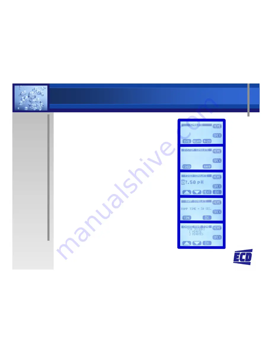
ECD T80 Manual Download Page 20

Simulation - System

System Simulate

T80 generates a 
signal equivalent to 
the PV signal

Enter Fixed Value

Ramp (↑ then ↓)

Ramp (↑ then ↓)

Cycles the Range 
from the low value 
to the high value 
and back.

Adjustable cycle 
time

Triggers Relays and 
varies 4-20 mA Out

Summary of Contents for T80

Page 1: ...T80 Universal Transmitter S80 Intelligent Sensors ELECTRO CHEMICAL DEVICES Presented by January 2012...

Page 2: ...T80 Universal Transmitter One Transmitter for Multiple Measurements pH ORP ORP Dissolved Oxygen All Specific Ions Conductivity Resistivity Turbidity...

Page 3: ...T80 Universal Transmitter Easy to Use Membrane Switch Navigation Simple Menu Structure Structure Soft Key Menu Choices Easy to read 2 x 1 LCD Display...

Page 4: ...tandard pH sensor with solution ground using the optional T80 input card Outputs 4 20 mA MODBUS RTU on 24 VDC MODBUS RTU on 24 VDC and 110 220 VAC instruments Optional HART 7 Optional 3 Alarm Relays P...

Page 5: ...Sensors New but Familiar Digital Communication with Transmitter Sensor Type Serial Number Process Variable Process Variable Temperature Calibration Data Waterproof IP68 rated Industrial Detachable Ca...

Page 6: ...1 Intelligent Sensor 2 Common Configuration for all Measurements 3 Application Specific Cartridges Cartridges 4 Economic and Easily Replaceable Cartridges 5 Submersible and Retractable designs 6 Appli...

Page 7: ...ome Screens Data Screen Process Variable 4 20 mA range Temperature mV Screen Raw mV signal from Raw mV signal from the sensor 4 20 mA range Temperature Graphical Screen 3 choices Line Bar Gauge Proces...

Page 8: ...ce except the Screen Key within 1 second to enter the Main Menu CAL Calibration CONFIG Configuration CONFIG Configuration INFO Information SIM Simulation HOLD Output Hold Function Toggles ON OFF Freez...

Page 9: ...sters NO Saves to top register Auto Calibration Two point Cal Automatically recognizes the Calibration Solution the Calibration Solution Standardize Single point adjustment Manual User entry of the Of...

Page 10: ...he calibration Press AUTO and Cal 1 and the T80 waits for a stable reading and then Suggests the value of the Suggests the value of the Calibration Standard Accept the value YES or enter a different v...

Page 11: ...d when the sensor stabilizes Accept the value or enter a different one The Calibration Offset and Slope values are and Slope values are displayed Press OK to exit the Calibration Mode and Exit to leav...

Page 12: ...tered manually Test an electrode in the shop and install it and enter the Cal Data in the field Enter the PV value Press Enter the PV value Press mV and enter the associated mV value Accept the entry...

Page 13: ...nfigure Transmitter LCD Display Contrast C F OUTPUT 4 20 mA Relays SERIAL SERIAL MODBUS or HART addresses PASSWORD Set Level and Password Configure Sensor Type of Sensor pH ORP Temp Compensation C Iso...

Page 14: ...ast Time Out for Back Light Soft Keys Text or Icons Line Gauge or Bar Graphs Line graph duration 1 minute 15 minutes 1 1 minute 15 minutes 1 hour 12 hours 1 day 2 days Tag 52 characters Tag On Display...

Page 15: ...4 mA 20 mA enter value HOME EXIT SAVE Calibrate the Output Transmitter sends out 4 mA signal Enter measured value press OK Enter measured value press OK Transmitter sends out 20 mA signal Enter measu...

Page 16: ...tion Alarm Set Point Fault Failure Alarm Disable Inactivates relay and removes Icon from Home Display Home Display Configure Alarm set point Set Point ON value Set Point OFF determines whether Hi Lo s...

Page 17: ...d Sets the Hold Time Out Function Serial Configuration Address MODBUS HART Baud MODBUS only Format MODBUS only Format MODBUS only Password Protection Choose Level Enter 4 character password case sensi...

Page 18: ...INFO T80 Transmitter Transmitter INFO Serial revision levels Hardware Software T80 Configuration T80 Configuration Relay configurations 1 3 4 20 Configuration...

Page 19: ...INFO S80 Sensor Sensor INFO Process Variable serial Firm ware revision Sensor s Range Sensor s Range Calibration Logs Logs 1 3 Offset Slope...

Page 20: ...m Simulate T80 generates a signal equivalent to the PV signal Enter Fixed Value Ramp then Ramp then Cycles the Range from the low value to the high value and back Adjustable cycle time Triggers Relays...

Page 21: ...4 20 mA Relay Simulation Puts the Relays under manual control Choose Relay and turn it ON or OFF 4 20 mA Simulation 4 20 mA Simulation Enter mA value for T80 to output That completes the Menus CAL CO...

Page 22: ...Wiring and Power Board Color Code and Connection type embossed into the protective Circuit Board cover 110 220 VAC 110 220 VAC Power Board AC In 24 VDC Out Optional preamp for mV mV TC TC SG input...

Page 23: ...T80 Universal Transmitter One Transmitter for All Measurements Loop Powered 24 VDC or 110 220 VDC or 110 220 VAC Options HART 7 or MODBUS RTU With or without 3 Alarm Relays...

Page 24: ...ensors 30 Internal Digital Converter Preamp Power Supply 0 Loop Powered Transmitter 1 24 VDC Powered Transmitter 2 110 220 VAC powered Transmitter Alarm Relays 0 No Relays 1 3 Form 1C 250 V 5A relays...

Page 25: ...ensors Noise free digital Communication Calibrated sensors Plug and Play Easy Maintenance IP68 Waterproof IP68 Waterproof Detachable Cable The same Electrode Cartridges Fittings and Hardware as the S1...

Page 26: ...Devices ECD has been a recognized leader in industrial process instrumentation recognized leader in industrial process instrumentation Liquid analytical sensors controllers transmitters analyzers and...

Reviews: