background image

P/N A51-4473-16


Page 

5


Rev 4.3.3


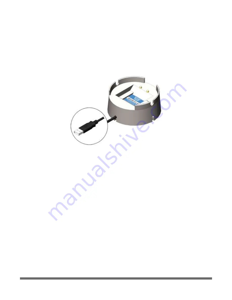
USB Dock Station 
 

The USB Dock Station is required for the MiniM.O.L.E.® rH to communicate with the M.O.L.E.® MAP 
software. The USB cable connects to a computer USB Port and then the user inserts the MiniM.O.L.E.® 
rH into the station cradle mating the brass contacts from both units. 


Summary of Contents for MiniM.O.L.E.

Page 1: ...P N A51 4473 16 Page 1 Rev 4 3 3 MiniM O L E rH Users Help Guide Rev 4 3 3...

Page 2: ...P N A51 4473 16 Page 2 Rev 4 3 3 Contents Equipment 3 Setup 7 Quick Start Guide 15 Service and Troubleshooting 21 Specifications 22...

Page 3: ...With LCD Display Magnet start 1 second to 10 day sample rate Features Functions Start Switch This is an internal switch that is triggered when using the Start Magnet Relative Humidity rH Temperature S...

Page 4: ...dy to record data Quick flashing Start Indicates Profiler is starting recording process Quick flashing Recording rH Indicates Profiler is recording rH data Flashing at log interval Recording Temperatu...

Page 5: ...USB Dock Station is required for the MiniM O L E rH to communicate with the M O L E MAP software The USB cable connects to a computer USB Port and then the user inserts the MiniM O L E rH into the sta...

Page 6: ...he unit by triggering an internal start switch This magnet is used only to initiate recording data after the unit is configured using the Setup Instrument wizard To Stop recording data the user downlo...

Page 7: ...onfigured to properly communicate with the M O L E MAP Software The M O L E MAP software must be installed prior to communications setup Refer to Software Installation for more information To connect...

Page 8: ...metallic contacts on the bottom of the M O L E Profiler are aligned with the contact pins on the USB Dock Station and that the M O L E Profiler is firmly seated Typically the device drivers are alrea...

Page 9: ...P N A51 4473 16 Page 9 Rev 4 3 3 3 Browse to the DriverMMrH Installer folder on the M O L E MAP Software installation CD...

Page 10: ...32 bit operating systems double click VCP_Driver_Installer exe For 64 bit operating systems double click VCP_Driver_Installer_x64 exe Depending on your operating system security settings a Security W...

Page 11: ...P N A51 4473 16 Page 11 Rev 4 3 3 5 VCP Driver Installer exe extracts DPInst exe and driver files into a temporary folder then starts the installation wizard 6 Click the Next command button...

Page 12: ...P N A51 4473 16 Page 12 Rev 4 3 3 7 The wizard starts device driver installation...

Page 13: ...ge 13 Rev 4 3 3 8 When the Installation has completed select the Finish command button 9 Start the software program by either double clicking the M O L E MAP software icon or selecting it from the ECD...

Page 14: ...M O L E MAP software allows multiple instruments to be connected to a computer at one time Selecting the Scan for Instruments command button will detect all instruments and display them in the dialog...

Page 15: ...the M O L E Profiler into the dock cradle Refer to the Communications Setup topic for your specific M O L E Profiler for more information 2 Set an Environment related for the type of experiment that i...

Page 16: ...he Scan for Instruments command button to detect all connected instruments If the software does not detect a M O L E Profiler using the communication cable connect it to the computer and click the Sca...

Page 17: ...N A51 4473 16 Page 17 Rev 4 3 3 6 Set instrument name recording interval and if the sensor is to be ON or OFF 7 Select the Next command button to send the data listed in the dialog box to the instrume...

Page 18: ...ocations and a product image This assembly information can then be loaded and saved from to a an XMA file Load This command buttons loads an existing assembly XMA Save This command button saves the cu...

Page 19: ...icking the Enlarge command button displays the Set Sensor Locations dialog box where the user can specify the locations of each sensor To move sensor locations drag the sensor markers to the approxima...

Page 20: ...ery charge internal temperature thermocouple temperatures If the user selects the Show Critical command button the dialog box will only display items that will prevent the user from completing a succe...

Page 21: ...links may be faulty If the problem occurs while attempting to use a software function the software may be faulty Once it has been determined what item is causing the problem refer to the appropriate...

Page 22: ...al Mechanical Spec PHYSICAL DIMENSIONS 0 37 in x 3 5 in x 6 in 9 41 mm x 89 mm x 152 4 mm TEMPERATURE MEASUREMENT RANGE 40 to 70 C 40 to 158 F RH RANGE 0 to 100 RH WARNING Exceeding this temperature m...

Reviews: