background image

Chengdu Ebyte Electronic Technology Co.,Ltd.

RS485

WiFi

NA611 User Manual

Copyright ©2012–2021

Chengdu Ebyte Electronic Technology Co.,Ltd.

4

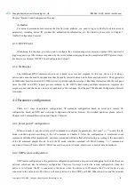
2.3 Software configuration

2.3.1 Device connection

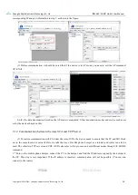
Figure 2-3-1 XCOM query connection parameters

Steps

(1) Open the serial port, find the corresponding device port number, the baud rate defaults to 115200-8N1,
click "open serial port".
(2) Send the "+++" command, and the serial port returns to "enter AT mode", indicating that the AT command
has been entered.
(3) Send

the

"AT+SSID?"

command,

and

the

serial

port

will

return

"AT+SSID=0,E103-W06-V1.1,2,12345678" to get the WIFI name and address required by the computer to
connect to the device later.
(4) Send the "AT+MODE?" command, the serial port returns "AT+MODE=1,1,1", if the serial port return
parameters are inconsistent with this, you need to send the "AT+MODE=1,1,1" command to modify the device
Working mode.
(5) Send the "AT+SVRPORTP?" command to query the IP address and port number of the next computer to

Summary of Contents for NA611

Page 1: ... RS485 WiFi NA611 NA611A ...

Page 2: ...cification 3 3 4 Dimension figure 4 3 5 Installation methods 4 4 Product function 错误 未定义书签 4 1 Job role 5 4 1 1 AP model Access Point 5 4 1 2 STA model Station 5 4 1 3 P2P model WiFi Direct 5 4 2 Transmission mode 5 4 2 1 Transparent transmission 5 4 2 2 Protocol transmission 6 4 3 Service mode 7 4 3 1 TCP Server 7 4 3 2 TCP Client 7 4 3 3 UDP 7 4 3 4 MQTT 7 4 3 5 HTTP Client 8 4 3 6 WebSocket 8 4...

Page 3: ...Communication between the roles STA and UDP 16 5 1 4 TCP communication between AP STA devices 20 5 1 5 UDP communication between devices 21 5 1 6 Set up the P2P communication of WiFi Direct 23 5 2 Network communication 24 5 2 1 MQTT 25 5 2 2 HTTP Client 27 5 2 3 WebSocket 28 5 3 Parameter configuration 28 5 3 1 Serial port AT instruction configuration 28 5 3 2 UDP remote communications 29 5 3 3 We...

Page 4: ...production use modification or disclosure to third parties of this document or any part thereof without the express permission of EBYTE is strictly prohibited The information contained herein is provided as is and EBYTE assumes no liability for the use of the information No warranty either express or implied is given including but not limited with respect to the accuracy correctness reliability an...

Page 5: ...k communication protocols Support TSL SSL secure transmission mode Support 4 way Socket connection Support 4 way STA device connection AP access point Support DNS DNS SD DHCP network service package Support AT command WeB web page parameter configuration Support NTP network time acquisition under the premise of internet access Support automatic reconnection after disconnection Support high speed c...

Page 6: ...i serial server hereinafter referred to as the device you need to prepare a computer converter power supply screwdriver and other related auxiliary materials details as follows Table 2 1 1 Preparation list No Device Quantity 1 Equipment 1 2 USB to serial converter 1 3 Computer 1 4 Power Adapter 12V 1A 1 5 WiFi antenna 1 6 Screwdriver Slot SL 2 1 2 2 Equipment wiring 2 2 1 Power supply wiring Power...

Page 7: ...iFi NA611 User Manual Copyright 2012 2021 Chengdu Ebyte Electronic Technology Co Ltd 3 2 2 2 Communications wiring RS485 Figure 2 2 2 Communication RS485 wiring diagram 2 2 3 Overall schematic diagram Figure 2 2 3 Schematic diagram of the whole machine ...

Page 8: ...mand and the serial port returns to enter AT mode indicating that the AT command has been entered 3 Send the AT SSID command and the serial port will return AT SSID 0 E103 W06 V1 1 2 12345678 to get the WIFI name and address required by the computer to connect to the device later 4 Send the AT MODE command the serial port returns AT MODE 1 1 1 if the serial port return parameters are inconsistent ...

Page 9: ... we use the network debugging assistant NetAssist to test the connection Steps 1 Select the network card where the WIFI is located and modify the configuration parameters of IPV4 The network segment where the computer is located must be consistent with the device as shown in Figure 2 3 4 2 Open the network debugging assistant NetAssist select the TCP Client mode the remote host address is 10 145 4...

Page 10: ...o Ltd RS485 WiFi NA611 User Manual Copyright 2012 2021 Chengdu Ebyte Electronic Technology Co Ltd 6 Figure 2 3 5 NetAssist parameter configuration Figure 2 3 6 Actual test results Send EBYTE TEST to observe the result of data communication ...

Page 11: ...nical parameters Project Parameter Operating Voltage Direct current 8 28V Alternating current 85 265V Communication Interface RS485 Working frequency 2 412GHz 2 472GHz 5 180GHz 5 825GHz Maximum transmit power 16dBm 18 5dBm testing 2 412GHz 16dBm 18 5dBm testing 5 18GHz Emission current 85mA 12V Instantaneous power consumption 2 412GHz DSSS 1Mbps 60mA 12V Instantaneous power consumption 5 18GHz OFD...

Page 12: ...power input port pressure line port 4 RS485 RS485 communication port Standard RS485 interface 5 PWR Power Indicator Lights up when the power is on 6 STATE Fault indicator Steady on equipment failure 7 DATA Data transceiver indicator Always off No data is sent or received Green light WIFI received data Red light The serial port receives data 8 LINKA WIFI connection indicator Steady on WIFI connecti...

Page 13: ...iFi NA611 User Manual Copyright 2012 2021 Chengdu Ebyte Electronic Technology Co Ltd 4 3 4 Dimension figure Figure 3 4 1 Dimensional drawing 3 5 Installation methods The equipment adopts the guide rail installation method Figure 3 5 1 Rail installation ...

Page 14: ... to 2 to configure the device to work in the STA role 4 1 3 P2P model WiFi Direct WiFi Direct mode is a way to establish a point to point connection directly without routing It is also called P2P which is similar to Bluetooth but the transmission rate is significantly higher than Bluetooth Command AT MODE 3 x x set the first digit to 3 to configure the device to work in WiFi Direct mode There are ...

Page 15: ...umber Fixed head Socket ID Data 3 Byte 1 Byte N Byte Fixed head 0xAA 0xFE 0x55 Socket ID Description 0x00 Socket 0 link 0x01 Socket 1 link 0x02 Socket2 link 0x03 Socket 3 link Data Application Payload 2 Broadcast transmission When the Socket ID is 0xff it means broadcast If a 4 way connection is established the data will be sent to the 4 way socket at the same time otherwise the data will be sent ...

Page 16: ...CP Client Let the device work as a TCP client Use command AT MODE x x 2 Set the third bit to configure the device to work in TCP client mode 4 3 3 UDP There is no distinction between server and client in UDP mode Use the command AT MODE x x 3 to set the third bit to configure the device to work in UDP mode In addition there is no concept of connection in UDP mode so the S_LINK pin will not be oper...

Page 17: ...ice can actively push data to the web page See Chapter 7 WebSocket Configuration Tutorial for details 4 4 Parameter configuration There are 3 ways of parameter configuration AT command configuration based on serial port remote AT configuration based on UDP and web page configuration based on browser For detailed operation please refer to Chapter 6 AT Command Description and Chapter 7 Tutorial 4 4 ...

Page 18: ...n indication includes WiFi connection status indication socket connection status indication and device abnormality indication When the WiFi connection is established the W_LINK pin outputs a high level and if the connection is disconnected the W_LINK outputs a low level When the socket connection is established S_LINK outputs a high level and if the connection is disconnected S_LINK outputs a low ...

Page 19: ...odbus function is turned on the protocol transmission is invalid that is the protocol transmission is no longer data with a fixed format and it will be converted to data that conforms to the modbus protocol standard 3 Only TCP server TCP client UDP MQTT WebSocket and P2P modes support Modbus protocol HTTP client does not support it The reason is because HTTP client is a short connection communicat...

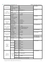
Page 20: ...ection parameters P2P Scan gap 20 AT P2PDEVINFO P2P role 0 client P2P Local name E103 W06WiFiDirectClient P2P Target name E103 W06WiFiDirectGo P2P socket P2P port 4001 AT P2PSOCKET P2P address 10 145 45 1 STAConnection parameters target SSID E103 W06 AT STACON Encryption type 2 password ebytew06 Connection Type 1 AT CONTYPE local Socket parameter Local port 4001 AT SVRPORTIP Local IP 10 145 45 1 R...

Page 21: ...0 145 45 1 AT IPSTATIC Subnet mask 255 255 255 0 Gateway address 10 145 45 1 server address 10 145 45 1 5 Instructions 5 1 Data transmission TCP UDP 5 1 1 PC communication Refer to this example TCP server UDP for the other two communications in TCP mode and set different modes through AT MODE command 1 Set device role AP transmission mode transparent transmission service mode TCP server AT MODE 1 ...

Page 22: ...ters restart the device find the SSID WiFi hotspot name set in the second step on the PC side and enter the Secret connection 7 After the connection is successful query the local IP and local port AT SVRPORTIP The return is as follows AT SVRPORTIP 4001 192 168 1 111 8 Open the TCP debugging assistant because the device is a server so create a client here and enter the ...

Page 23: ... this 5 1 2 Communication between the roles STA and TCP Server 1 To realize communication with PC under the role of STA the device needs to ensure that the PC and MO block are in the same local area network Here we take the way of mobile phone hotspot as a tutorial and router can also be used The other two TCP servers and UDP of STA also refer to this process and set different modes through AT MOD...

Page 24: ...efer to the instruction configure and read the SOCKET port IP address AT SOCKET 0 4001 192 168 43 64 4 Set device role STA transmission mode transparent transmission service mode client AT MODE 2 1 2 5 Set the connection target parameters The parameters here are the hotspot name password and encryption method set in the first step AT STACON ebytew06 2 12345678 6 Set the connection method connectio...

Page 25: ...Communication between the roles STA and UDP This example will demonstrate protocol transmission in AP mode 1 Setting role AP transmission mode protocol transmission service type UDP AT MODE 1 2 3 2 Set the local port number AT SVRPORTIP 4001 3 Set the UDP communication list This step is to distinguish the source of UDP data 4 groups can be set AT SOCKET 0 4001 10 145 45 2 AT SOCKET 1 4002 10 145 4...

Page 26: ...echnology Co Ltd RS485 WiFi NA611 User Manual Copyright 2012 2021 Chengdu Ebyte Electronic Technology Co Ltd 17 4 Restart the device and use the PC to connect to the device 5 Open the UDP assistant to establish UDP communication ...

Page 27: ...ation because it is a protocol transmission it is necessary to input data according to the protocol transmission format when sending data on the device side For details see Protocol Transmission The PC side does not need to add a format but the device will print out the data according to the protocol format after receiving the data from the PC side ...

Page 28: ...tion between the device and the PC is complete Both the AP and STA roles support TCP server TCP Client and UDP The specific combination can be used in conjunction with these three tutorials It should be noted that if the source address and port of the received data are not in the parameters set in the third step the serial port number is 0xff which means that the data source is not recognized ...

Page 29: ...nd communication cannot be established normally Regarding the channel and frequency settings because the devices are dual frequency 2 4G and 5 8G it is also necessary to ensure that the frequencies of the two devices are the same AP configuration Mode AT MODE 1 1 1 SSID AT SSID 0 E103 W06 2 12345678 Get the local IP AT SVRPORTIP This operation must be performed here and then pass the parameters in...

Page 30: ...tration STA1 configuration process Mode AT MODE 2 1 1 Target AT STACON E103 W06 2 12345678 Configure the local port AT SVRPORTIP 4001 Get IP address AT SVRPORTIP Get back AT SVRPORTIP 4001 192 168 0 189 STA2 configuration process Mode AT MODE 2 1 2 Target AT STACON E103 W06 2 12345678 Set the remote IP and port here the IP and port obtained by STA1 are passed in AT SOCKET 0 4001 192 168 0 189 Rest...

Page 31: ...DE 2 1 3 Set the target SSID AT STACON E103 W06 2 12345678 Set connection method AT CONTYPE 1 Set the local port AT SVRPORTIP 4002 note that the local port here is the remote port from the previous step Set the remote port remote IP AT SOCKET 0 4001 10 145 45 1 the remote port IP here is the local port IP in the previous step 3 Restart the device wait for connection and communicate ...

Page 32: ... select one of the devices to configure as GroupOwner and send instructions to set connection parameters see configuration and read WiFi Direct P2P connection parameters for instructions AT P2PDEVINFO 20 1 E103 W06WiFiDirectGo E103 W06WiFiDirectClient 3 Query the local port and IP address of the socket or AT P2PSOCKET 4 Finally configure another device as Client and send instructions to set connec...

Page 33: ...ust be obtained after querying the GroupOwner otherwise communication cannot be established AT SVRPORTIP 4001 10 145 45 1 6 Restart and wait for the connection to be established to communicate 5 2 Network communication Network communication is based on the STA role and communication with various cloud platforms including Alibaba Cloud Baidu Cloud OneNet based on MQTT HTTP servery and WebSocket ...

Page 34: ...g in to the web page in the mode setting menu select the work role as Station and the service mode as MQTT and save the settings In the parameter setting menu select Alibaba Cloud Product key In the console of the Alibaba Cloud IoT platform create a product and device to obtain a product key Such as A1Ve0iJW6z1 Device name The device name entered when adding a device Note Only numeric English can ...

Page 35: ...rnet of Things Port Baidu Internet of Things port Such as 1883 Subscribe to topics such as baidu iot general get Release topic such as baidu iot general update Subscribe to publish message levels Qos 0 Qos 1 Qos 2 1 OneNet Log in to the web page in the mode setting menu select the work role as Station and the service mode as MQTT and save the settings Log in to the web page again and select ONENET...

Page 36: ...method can be post or get 4 All output is selected as the output mode the content of the server s reply is all output through the serial port and the valid output is selected and the serial port only outputs valid data 5 Enter the URL path of the header 6 User defined input protocol header if multiple entries need to be added directly r ndo not add the last one If the user passes parameters via GE...

Page 37: ...inal release must be deleted and the blank line is reserved username test userpwd 123456 Among them request login do is the content set in the header path URL and name test userpwd 123456 is the data received by the device serial port 192 168 4 10 8080 is the HTTP server address and port Custom protocol header The default is Connection keep alive which can be modified by the user If more than one ...

Page 38: ...re in the same LAN For the configuration method see the communication with the PC either make the device in AP mode and the PC connects to the device or make the device in STA mode and the PC connect to the same router to obtain the IP After the address directly enter the IP address and UDP port number 8009 this port number is a fixed value and does not support changing The remote configuration is...

Page 39: ...ddress in the browser Here 10 145 45 1 is just the IP address used for demonstration the specific IP address Please use the command AT SVRPORTIP to query and enter the correct IP to enter the configuration interface The IP address is set according to the feedback result of the device and other parameters are set according to your own needs 5 3 4 Modbus use After setting the working parameters acco...

Page 40: ... 31 The MODBUS function of this device only supports protocol conversion between MODBUS RTU and MODBUS TCP If necessary please use it in combination with actual use The final interpretation right belongs to Chengdu Ebyte Electronic Technology Co Ltd Revision history Version Date Description Issued by 1 0 2021 03 16 Initial version ken ...

Page 41: ...ogy Co Ltd 32 About us Technical support support cdebyte com Documents and RF Setting download link www ebyte com Thank you for using Ebyte products Please contact us with any questions or suggestions info cdebyte com Phone 86 028 61399028 Web www ebyte com Address B5 Mould Park 199 Xiqu Ave High tech District Sichuan China ...

Reviews: