Chengdu Ebyte Electronic Technology Co., Ltd.
【
4DI+2DO
】
MA01-AXCX4020 User Manual
Copyright ©2012–2023, Chengdu Ebyte Electronic Technology Co., Ltd.
14
4.2.2 Switch output DO mode setting
(1) Level mode
Output according to the level set by the user. The switching characteristics of the level mode are
similar to the function of a self-locking switch.
(2) Pulse mode
After the switch output DO is turned on, the set pulse width time (in ms) is maintained, and the
switch output DO is automatically turned off. The pulse width setting range is 50
~
65535 (default
50).
(3) Follow mode
After the user sets the follow mode, set the follow input terminal. The switch output DO
terminal is consistent with the DI input terminal.
Note: Multiple switch output DO terminals can be set to follow one DI input terminal, and one
switch output DO terminal can not be set to follow multiple DI input terminals.
4.3 Device address
4.3.1 Device address
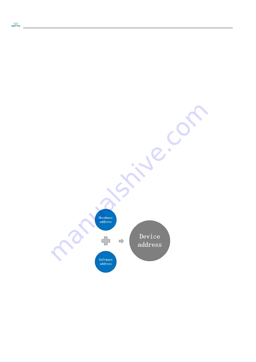
Device address composition: hardware a software offset address
Figure 4-3-1 Device address
The default device address is: 1 (hardware address 0 + software address 1 = device address 1).
Device address setting range: 1
~
247.
Hardware address: realized by the dial switch (5 digits) dial setting (the factory default is 0).
Software address: It is realized by the "offset address" set by the configuration tool software (the
factory default is 1).
For example:
If the hardware address is set to 5 and the software address is set to 113, the device address is 118.
Summary of Contents for MA01-AXCX4020
Page 1: ...4DI 2DO MA01 AXCX4020...


