Ebyte ECAN-U01S User Manual Download Page 10

Chengdu Ebyte Electronic Technology Co.,Ltd.

ECAN-U01S User Manual

Copyright ©2012–2022,Chengdu Ebyte Electronic Technology Co.,Ltd.

10

5

Communication

Interface

USB

Type B USB interface

6

CAN baud rate

Factory default 100K

——

6. Equipment usage

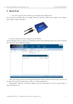
6.1. Connect with PC

The USB interface of ECAN-U01S conforms to the USB2.0 full-speed protocol specification, and can communicate with
PCs with USB1.1 and USB2.0 standards.

6.1.1. USB Bus Power Mode

The USB bus powered mode is suitable for most applications, for example, when the ECAN-U01S is the only

device connected to the USB port. Connect the PC and ECAN-U01S directly through the supplied USB cable, and supply
+5V power to ECAN-U01S from the USB cable . At this time, the indicators PWR and Work are on, indicating that the
device is working normally and is in the state to be connected.

6.1.2.

External power supply mode

The external power supply mode is suitable for the occasions where the PC uses a USB bus hub ( HUB ), or has

connected multiple USB terminal devices, so that the USB port cannot provide enough current to the ECAN-U01S .

Use an external power supply (DC8-28V) to connect to the power socket of ECAN-U01S , at this time the indicators

PWR and Work are on ; then connect the PC and ECAN-U01S through the supplied USB cable, ECAN-U01S can work
normally.

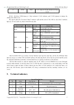
6.2. Connectwith CAN-bus

When ECAN-U01S is connected to the CAN bus, you only need to connect CAN_H to CAN_H and CAN_L to

CAN_L to establish communication.

The CAN-bus network adopts a linear topology, and the two farthest terminals of the bus need to be installed with

120 Ω terminal resistance; if the number of nodes is greater than 2 , the intermediate node does not need to be installed
with a 120 Ω terminal resistance. For branch connections, its length should not exceed 3 meters. The connection of
CAN-bus is shown in the figure.

Summary of Contents for ECAN-U01S

Page 1: ...1 ECAN U01S...

Page 2: ...rs 9 General Specifications 9 6 Equipment usage 10 6 1 Connect with PC 10 6 2 Connectwith CAN bus 10 6 3 CAN bus terminating resistor 11 7 Function details 11 7 1 Save data and real time save function...

Page 3: ...nd has its own B type USB interface each channel has a built in 120 ohm optional resistance which is controlled by a DIP switch which is convenient to use integrated CAN interface electrical isolation...

Page 4: ...g to their needs 2 Connect the computer to the device through a Type B USB cable Open the debugging software and enter the communication interface after configuring parameters such as the CAN baud rat...

Page 5: ...rt number You need to select the serial port number corresponding to the device 2 Open Device button Click this button to access the USBCAN device If USB device open error is displayed please check wh...

Page 6: ...e that it is especially important to set the baud rate Many customers report that there is no data after the device is connected or the bus is wrong In fact the baud rate is not set so click OK to ope...

Page 7: ...1S User Manual Copyright 2012 2022 Chengdu Ebyte Electronic Technology Co Ltd 7 3 Installation size Equipment dimensions length including terminals mm width mm height mm the schematic diagram is shown...

Page 8: ...e position and definition of each interface of ECAN U01S are shown in the figure Pins from left to right Port Name Function 1 DC 8 28V DC8 28V USBCAN auxiliary power supply generally do not need to be...

Page 9: ...green Corresponding to CAN channel bus error After the ECAN U01S is powered on the four indicators light up at the same time and then the PWR and Work lights are always on but the CAN1 and CAN2 light...

Page 10: ...be connected 6 1 2 External power supply mode The external power supply mode is suitable for the occasions where the PC uses a USB bus hub HUB or has connected multiple USB terminal devices so that t...

Page 11: ...ors Note ECAN U01S has integrated 120 terminal resistance you can choose whether to connect the resistance to the bus through the DIP switch the DIP switch is next to the 6pin terminal R1 R2 correspon...

Page 12: ...chnology Co Ltd 12 data from the start A to the end B are written to the save file 7 2 Pause display function Click Pause to pause the currently scrolling data window The device and software can still...

Page 13: ...splay Mode The display mode supports scrolling mode to display the received or sent data The scrolling display means that the received data scrolls down continuously in the receiving list and the curr...

Page 14: ...tware will only display the set filter conditions and frames that are not within the filter range will be filtered out The demo is as follows 7 6 Bus diagnostic function When a bus error occurs during...

Page 15: ...ansmission mode 8 1 Normal sending mode In the normal mode the frame data to be sent can be edited very intuitively and special functions such as cyclic sending can be set Editing frame information is...

Page 16: ...s improvement of the hardware and software of the product this manual may be changed without prior notice and the latest version of the manual shall prevail Everyone is responsible for protecting the...

Page 17: ...7 About us Technical support support cdebyte com Documents and RF Setting download link https www cdebyte com Thank you for using Ebyte products Please contact us with any questions or suggestions inf...

Reviews: