background image

Chengdu Ebyte Electronic Technology Co,;Ltd                                                                                                                                    E70-915T30S user manual


Copyright ©2012–2019

Chengdu Ebyte Electronic Technology Co,;Ltd                                                                                                                                5 


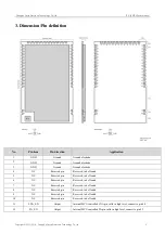
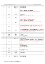
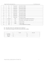
3. Dimension/Pin definition 


No. 

Pin item 

Pin direction 

Application 

GND 

Ground 

Ground electrode 

GND 

Ground 

Ground electrode 

GND 

Ground 

Ground electrode 

NC 

Reserved pin 

Reserved, to be floated 

NC 

Reserved pin 

Reserved, to be floated 

NC 

Reserved pin 

Reserved, to be floated 

NC 

Reserved pin 

Reserved, to be floated 

NC 

Reserved pin 

Reserved, to be floated 

NC 

Reserved pin 

Reserved, to be floated 

10 

NC 

Reserved pin 

Reserved, to be floated 

11 

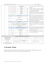
LNA_EN 

Output 

Internal MCU controlled LNA pin, valid in high level, connect to pin 44 

12 

PA_EN 

Output 

Internal MCU controlled PA pin, valid in high level, connect to pin 45 

Summary of Contents for E70-915T30S

Page 1: ...E70 915T30S User Manuel CC1310 915MHz 1W SMD Wireless Module...

Page 2: ...ation of wireless transmitting 10 5 6 3 Configuration procedure of module 11 6 OPERATING MODE 11 6 1 MODE SWITCH 12 6 2 RSSI MODE MODE 0 13 6 3 CONTINUOUS MODE MODE 1 13 6 4 SUB PACKAGE MODE MODE 2 14...

Page 3: ...du Ebyte Electronic Technology Co Ltd 2 12 PRODUCTION GUIDANCE 25 12 1 REFLOW SOLDERING TEMPERATURE 25 12 2 REFLOW SOLDERING CURVE 25 13 E70 SERIES 26 14 ANTENNA GUIDANCE 26 14 1 ANTENNA RECOMMENDATIO...

Page 4: ...functional wireless serial program users can also according to the need for secondary development 1 2 Features Communication distance tested is up to 6km Maximum transmission power of 1W software mult...

Page 5: ...rating temperature 40 85 Industrial design Operating frequency MHz 907 922 5 Support ISM band Power consumption Transmitting current mA 600 Instant power consumption Receiving current mA 14 Turn off c...

Page 6: ...und electrode 4 NC Reserved pin Reserved to be floated 5 NC Reserved pin Reserved to be floated 6 NC Reserved pin Reserved to be floated 7 NC Reserved pin Reserved to be floated 8 NC Reserved pin Rese...

Page 7: ...refer to Parameter setting An external 1k protective resistor shall be connected in series when in use 21 TXD Output TTL serial port output connecting to external RXD input pin It can be configured as...

Page 8: ...loated 41 NC Reserved pin Reserved to be floated 42 NC Reserved pin Reserved to be floated 43 NC Reserved pin Reserved to be floated 44 LNA_EN Input Internal LNA pin valid in high level connect to pin...

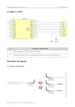
Page 9: ...019 Chengdu Ebyte Electronic Technology Co Ltd 8 4 Connect to MCU No Description STM8L MCU 1 The UART module is TTL level please collect with MCU 2 For some MCU works at 5VDC it may need to add 4 10K...

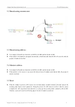
Page 10: ...address For example Set the address of module A as 0xFFFF or 0x0000 and the channel as 0x04 When module A is the receiver it can receive the data sent from all modules under channel 0x04 the purpose o...

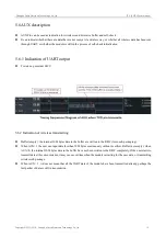
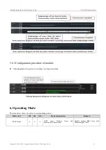
Page 11: ...wake up external MCU 5 6 2 Indication of wireless transmitting Buffer empty the internal 1024 bytes data in the buffer are written to the RFIC Auto sub packaging When AUX 1 the user can input data le...

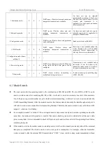
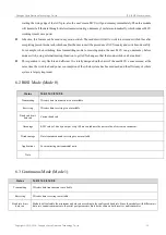
Page 12: ...Configuration procedure of module Only happened when power on resetting or exiting sleep mode 6 Operating Mode The table below shows the status of corresponding modes Mode 0 7 M2 M1 M0 Mode introduct...

Page 13: ...er consumption receiving 7 Sleep mode 1 1 1 UART closes wireless transmitting is available and sleep mode is on It can be woken up by any falling edge of M2 M1 M0 6 1 Mode Switch The user can decide t...

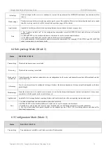
Page 14: ...and efficient It is totally designed on the basis of the user MCU s convenience at the same time the work load and power consumption of the whole system has been reduced and the efficiency of whole s...

Page 15: ...1 M2 0 Transmitting Wireless data transmission is available Receiving Wireless data receiving is available Baud rate air data rate Under this mode the baud rate and air data rate are independent both...

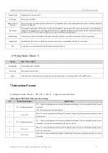
Page 16: ...the receiver under mode 6 wake up code will be added automatically before transmitting the code number depends on the wake up time Disadvantage The transmission time is long only applicable to wake up...

Page 17: ...ta sent from the transmitter under mode 4 6 9 Sleep Mode Mode 7 Status M0 1 M1 1 M2 1 Transmitting Transmitting is not available Receiving Receiving is not available Others Other functions of the modu...

Page 18: ...X5 70 here means the module model E70 series xx1 is the version number and XX2 XX3 XX4 XX5 refers to the other module features 7 4 Reset Instruction Instruction format Description C4 C4 C4 In configur...

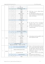
Page 19: ...kbps 0 1 0 12kbps Default 0 1 1 28kbps 1 0 0 64kbps 1 0 1 168kbps 1 1 0 168kbps 1 1 1 168kbps 4 CHAN 7 6 5 Packet length only for subpackage mode Under continuous transmitting mode M0 1 M1 0 M2 0 this...

Page 20: ...de This bit is used to the internal pull up resistor It also increases the level s adaptability in case of open drain But in some cases it may need external pull up resistor 0 TXD and AUX push pull ou...

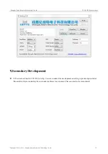
Page 21: ...19 Chengdu Ebyte Electronic Technology Co Ltd 20 9 Secondary Development E70 series have built in CC1310 SoC chip Users can conduct the development according to pin description below Meanwhile Ebyte c...

Page 22: ...nce ground Ground electrode 4 X32K_Q1 Input Output Connect to 32 768K quartz crystal with pin 5 5 X32K_Q2 Input Output Connect to 32 768K quartz crystal with pin 4 6 DIO_1 Input Output MCU GPIO 7 DIO_...

Page 23: ...tage range 2 6V 5 5V DC 30 GND Reference ground Ground electrode 31 GND Reference ground Ground electrode 32 DIO_19 Input Output MCU GPIO 33 DIO_20 Input Output MCU GPIO 34 DIO_21 Input Output MCU GPI...

Page 24: ...n recommended to reserve more than 30 of the margin so the whole machine is beneficial for long term stable operation The module should be as far away as possible from the power supply transformers hi...

Page 25: ...testing near ground Sea water has great ability in absorbing wireless radio wave so performance will be poor when testing near the sea The signal will be affected when the antenna is near metal object...

Page 26: ...6 5 Ag3 Cu0 5 Preheat Temperature min Tsmin 100 150 Preheat temperature max Tsmax 150 200 Preheat Time Tsmin to Tsmax ts 60 120 sec 60 120 sec Average ramp up rate Tsmax to Tp 3 second max 3 second ma...

Page 27: ...S CC1310 868M 30 6 2 5k 168k SMD 24 38 5 IPEX Stamp hole E70 433T30S CC1310 433M 30 6 2 5k 168k SMD 24 38 5 IPEX Stamp hole E70 433T14S CC1310 433M 14 1 5 2 5k 168k SMD 16 26 IPEX Stamp hole E70 868T1...

Page 28: ...tronic Technology Co Ltd 27 14 2 Antenna Choosing Factory default welding of 0R resistance is shown in the figure left The antenna interface is IPEX If you need to change the antenna interface into a...

Page 29: ...content updating huaa 1 20 2018 05 24 content updating Huaa 1 21 2018 07 20 name change Huaa 1 30 2018 10 29 module separating Huaa About us Technical support support cdebyte com Documents and RF Sett...

Reviews: