


Chengdu Ebyte Electronic Technology Co., Ltd.
E22-400T30S_User Manual _EN
Copyright ©2012–2020, Chengdu Ebyte Electronic Technology Co., Ltd.
8
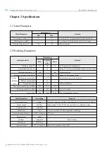
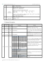
10
C2D
Input
Data pin when the program is loaded (dangling, users do not need to connect)
11
+3.3V
Input
The power supply pin when the program is loaded (the user does not need to
connect, it is floating)
12
P2.7
Input/ Output
NC pin, this pin needs to be suspended (for subsequent expansion)
13
P1.5
Input/ Output
NC pin, this pin needs to be suspended (for subsequent expansion)
14
P1.6
Input/ Output
NC pin, this pin needs to be suspended (for subsequent expansion)
15
GND
-
Fixedly
16
GND
-
Fixedly
17
GND
-
Fixedly
18
ANT
Output
Antenna interface (high-frequency signal output, 50Ω characteristic
impedance)
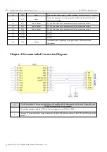
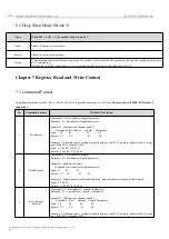
Chapter 4 Recommended Connection Diagram
No.
A brief description of the connection between the module and the microcontroller (the above figure takes the
STM8L microcontroller as an example)
1
The wireless serial port module is TTL level, please connect it with TTL level MCU.
2
For some 5V microcontrollers, it may be necessary to add 4-10K pull-up resistors to the TXD and AUX pins of the
module.