Chengdu Ebyte Electronic Technology Co., Ltd.
E103-W01 User Manual
Copyright ©2012–2018
Chengdu Ebyte Electronic Technology Co., Ltd.
5
5
GPIO14
IO
PWM1/GPIO14
6
GPIO12
IO
PWM0/GPIO12
7
GPIO13
IO
GPIO13
8
VCC
-
VDC:3.0V~3.6V
(
above 300mA
)
9
GND
-
GND pin
10
GPIO15
I
GPIO15
GPIO2
★
GPIO0
Boot
11
GPIO2
I
0
1
1
Boot from
FLASH
12
GPIO0
I
0
1
0
Download
firmware from
UART
13
GPIO4
IO
PWM2/GPIO4
14
GPIO5
IO
PWM3/GPIO5
15
RXD
I
UART input pin, support AT command
16
TXD
O
UART output pin, support AT command
★
GPIO2 is already been internal pulled up
★ In transparent-transmission on power-up mode, GPIO2 will indicate the status of module. The module has
connected a led to this pin. Users can get the status of the module by observing LED. Besides, you may connect GPIO2
to the external MCU.
★ LED indication when module works in power-on transparent transmission mode
:
Intermittent double flash
:
cannot connect to AP access point.
Intermittent single flash
:
connect to AP access point, but cannot connect to TCP server.
Quench
:
connect to AP access point and TCP server.
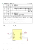
4 Recommended connection diagrams
Note
:
supply voltage is 3.0V~3.6V. 500mA LDO is recommended for steady operation of module.

