background image

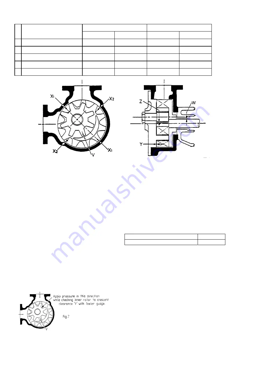
TABLE OF CLEARANCES 

Metallic

Carbon 


          Running Clearances


'A' 

CLEARANCE

'B' 

CLEARANCE

'A' 

CLEARANCE

'B' 

CLEARANCE


 Diametral - Rotor Pin to Bearing 

 0.12-0.16 mm

0.12-0.16 mm

0.09-0.13mm

0.09-0.13mm 

 Axial - Rotors to Cover 

 0.13-0.18 mm

0.17-0.22 mm

0.13-0.18 mm

0.17-0.22 mm 

 Diametral - Outer Rotor to Body 

 0.28-0.38 mm

0.40-0.53 mm

0.28-0.38 mm

0.40-0.53 mm 

W   Diametral - Shaft to Bearing 

 0.10-0.14 mm

0.13-0.16 mm

0.08-0.11mm

0.10-0.14mm 

 Radial - Inner Rotor to Crescent 

 0.03-0.08 mm

0.03-0.08 mm

0.02-0.06mm

0.02-0.06mm 


Figure 6 

 
6. 

Carry out preliminary sizing checks: 


a)  Axial length of Inner Rotor, Outer Rotor teeth 

and Cover crescent must be matched to within 
+/- 0,02mm. 


b)  Outer Rotor in Body diametral clearance. Note: 

If checking by feeler gauge method, allowance 
or compensation must be made for eccentricity 
caused by: 


i)  Weight of Rotor.  


ii) Clearances between Shaft and Bracket 

Bearing. 


iii)  Lack of Bearing support at drive end 


6


To measure clearance, insert feeler gauge at 
two opposite measurement points 'X

1

'. Add the 

two clearances together. This will give the 
diametral clearance 'X' for the two points. 
Repeat this procedure for the other two 
measurement points 'X

2

'. 


c)  To check clearance between Inner Rotor and 

Cover crescent, Inner Rotor should be held 
towards inlet plane. Refer Fig. 7 


7. 

Ensure all lubrication/cooling circulation 
harness assemblies are clear of any 
obstructions. 

8. 

EBSRAY recommend replacement of all 
Gaskets, Seals and "O"rings at every  overhaul, 
to ensure positive sealing.  


4.6


REASSEMBLY 

(Refer Drg No. CMP051) 

 
TORQUE SETTINGS


Cover to Body Studs and Nuts 

203.4 Nm 

Bracket to Body Setscrews: 

203.4 Nm 


During reassembly, lubrication is required in some 
areas. All lubrication in areas where it may come into 
contact with pumped product should be with a 
product compatible lubricant. The Bracket Ball 
Bearing and lockring Seals may be lubricated with 
any high quality lithium base grease suitable for the 
operating conditions. 

1.


(For pumps fitted with SJ Cover Plate only)


Using a new Cover Gasket, locate the SJ Cover 
Plate on the Cover with the Inner Rotor Pin bores in 
alignment and temporarily fasten the two together 
using bolts of the same diameter as the Cover 
bolts. After fastening Inner Roror Pin (Step 4) 
remove these temporary bolts.  

2. 

Fit Inner Rotor Pin Gasket to the Inner Rotor Pin 
locating step. 

Summary of Contents for HD600

Page 1: ... INSTALLATION OPERATION MAINTENANCE INSTRUCTIONS FOR EBSRAY MODEL HD600 ROTARY INTERNAL GEAR PUMP EBSRAY PUMPS PTY LIMITED ACN 000 O61 003 628 PITTWATER RD BROOKVALE NSW 2100 AUSTRALIA PH 61 2 9905 0234 FAX 61 2 9938 3825 ...

Page 2: ...n and the carrier s copy of the consignment note and a claim should be made immediately on the transport company Should a shortage be evident on receipt notify EBSRAY immediately giving full details and packing note number 1 5 HANDLING Do not drop pump pumpset Care should be taken in moving handling pumps pumpsets A sling should be placed under or around a pump pumpset in order to minimise stress ...

Page 3: ...hich are not involved in the meshing cycle are sealed by the crescent C Body and Cover Refer Fig 5 3 2 PUMPING PRINCIPLE When rotation is started there is an increase in cell volume as the teeth come out of mesh This creates a partial vacuum and the pressure differential thus created initiates movement of the liquid through the inlet port D filling the teeth cells of the two displacement rotors Wh...

Page 4: ... maintained for extended periods particularly with integral Bypass Valve The Bypass Valve should be set on site in accordance with the predetermined pump and or system differential pressure required Refer separate instructions SECTION 4 MAINTENANCE CAUTION PRIOR TO ANY DISASSEMBLY OR SERVICE VERIFY THAT ALL REQUIREMENTS OF STATUTORY REGULATIONS OR CODES ARE MET AND THAT SPECIFIC SITE REQUIREMENTS ...

Page 5: ...d Rotor Bearing if replacement is required 4 4 INSPECTION Inspect components for damage or excessive wear Note that typical wear of components in EBSRAY s rotary Internal Gear positive displacement pumps tend to compensate each other and working clearances are to some extent maintained by this compensation If pump performance has been satisfactory existing components although worn may still have a...

Page 6: ...iametral clearance X for the two points Repeat this procedure for the other two measurement points X2 c To check clearance between Inner Rotor and Cover crescent Inner Rotor should be held towards inlet plane Refer Fig 7 7 Ensure all lubrication cooling circulation harness assemblies are clear of any obstructions 8 EBSRAY recommend replacement of all Gaskets Seals and O rings at every overhaul to ...

Page 7: ...adjusted correctly are designed to have a very small amount of seepage If packing is too tight it will generate excessive heat if too loose it will leak excessively 12 Lubricate Lipseal on Inner Lockring and slide Lockring along Shaft screw Lockring in until it protrudes approximately 4mm from thread on pump side 13 Lubricate Bracket Ball Bearing Fit Bearing to Shaft and drive Bearing into positio...

Page 8: ...ody and re machine or replace 2 Check Valve for damage or deposits Clean thoroughly or replace Valve as required If worn or if seat or Valve is damaged lap cleaned replaced Valve into valve seat 3 Inspect Bypass Valve Spring Replace if broken or damaged 4 It is advised that all gaskets be replaced whenever disassembled 5 Check Cap Washer Adjusting Screw and Locknut for damage Replace as required 5...

Page 9: ...r discharge pipes of insufficient diameter causing excessive friction loss 5 Bypass valve pressure setting too low Increase pressure by screwing in adjusting screw DO NOT exceed pump or system design pressure or overload motor etc 6 Insufficient NPSH available 7 Excess axial clearance setting of rotor to cover 8 Excess clearances in pump due to wear 6 3 EXCESSIVE POWER CONSUMPTION 1 Differential p...

Page 10: ...alve Spring 1 54 Bypass Valve Lock Nut 1 55 Bypass Valve Adjusting Screw 1 56 Bypass Valve Adjusting Screw Cap 1 56A Gasket Adjusting Screw Cap 1 57 Bypass Valve Gasket 2 60 Inner Rotor 1 61 Inner Rotor Bearing 1 62 Inner Rotor Pin 1 63 Inner Rotor Pin Nut 1 64 Inner Rotor Pin Washer 1 64A Inner Rotor Pin Spacer 1 68 Bracket 1 69 Rotor Bearing 1 69A Extraction Washer 1 69B Extraction Washer O ring...

Page 11: ...11 11 ...

Reviews: