Publication # 2080-04
EBSRAY PUMPS
INSTALLATION, OPERATION & MAINTENANCE INSTRUCTIONS
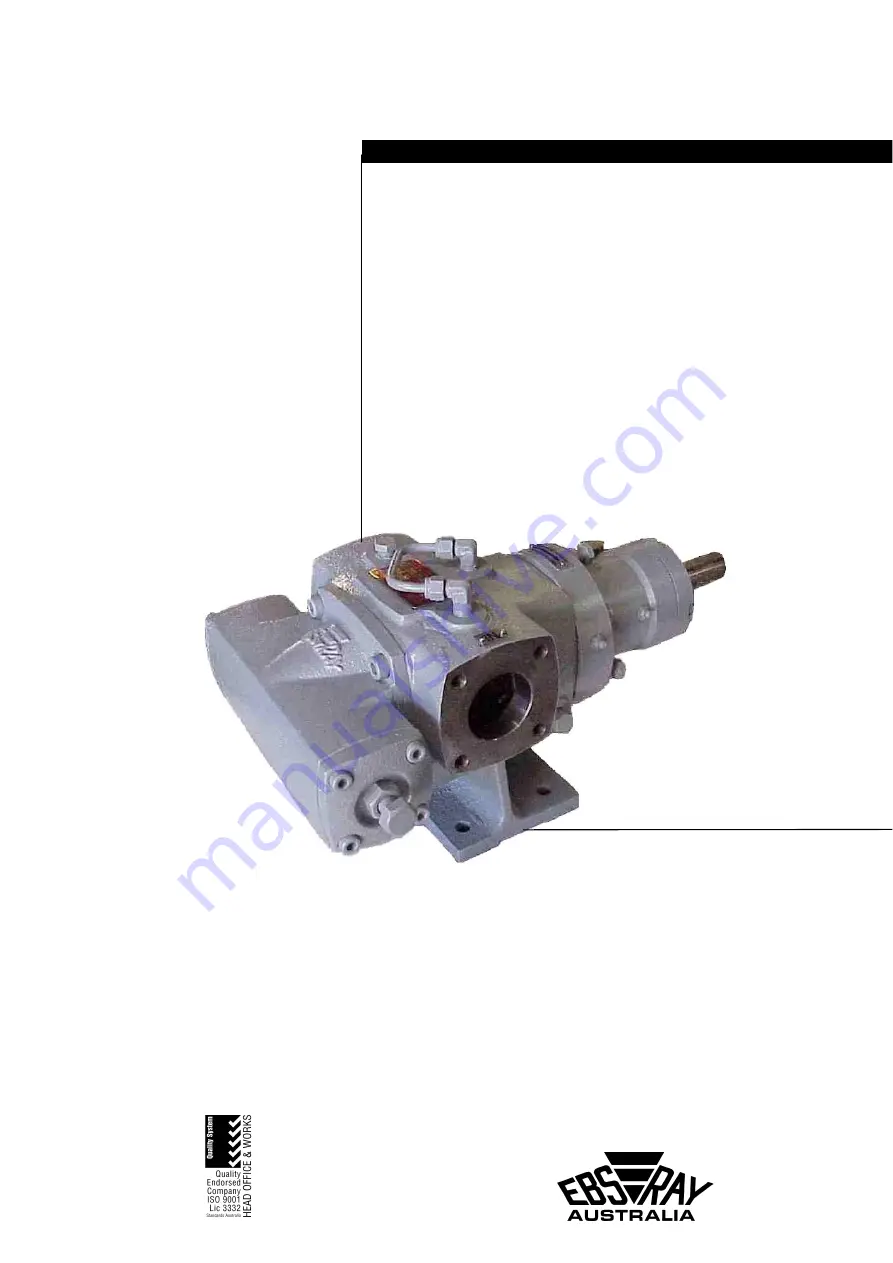
E SERIES
MODEL E20HD
Page 1: ...Publication 2080 04 EBSRAY PUMPS INSTALLATION OPERATION MAINTENANCE INSTRUCTIONS E SERIES MODEL E20HD...
Page 2: ...uld be stored in a dry covered area If storage is required for other than a short period prior to installation special preservatives and protective wrappings will be required 1 4 INSPECTION ON RECEIPT...
Page 3: ...data for specific coupling types Figure 1 Figure 2 ANGULAR MISALIGNMENT as shown in Fig 1 should be corrected before eccentricity Refer Fig 3 Use feeler gauge reading at 90 intervals the amount of co...
Page 4: ...ars to minimise tooth wear The inner rotor B or idler remains in almost hydraulic balance requiring only minimal torsional load to effectively follow the outer drive rotor 3 3 APPLICATIONS The field o...
Page 5: ...umber and quantity required Refer to Drawing No A300001H 3 Advise complete delivery instructions transport company etc 4 2 PREPARATION FOR DISASSEMBLY 1 Obtain the appropriate Work Permit if required...
Page 6: ...ne with reconditioning to an as new status as replacing or repairing one component will have an effect on other components and the working clearances of the pump 4 5 REASSEMBLY PRELIMINARY For dimensi...
Page 7: ...over shaft apply a medium strength thread locking adhesive Loctite 243 or equivalent to the two grubscrews and lock into position ensuring grubscrews locate in groove of shaft 3 Fit mechanical seal st...
Page 8: ...Adjust shim quantity until clearance is set to 0 05 to 0 08 mm 17 Loosen bearing carrier capscrews and slowly tighten adjustment screws until rotor is pulled back in body Assemble inner rotor over in...
Page 9: ...oltage and phases b If engine driven check governor setting and engine speed 4 System discharge head too high check system head friction losses and bypass valve setting 5 Excessive suction restriction...
Page 10: ...g suction line restrictions created by i Inadequate pipe sizes excessive line lengths ii Incorrect selection of valves fittings etc iii Strainer not permitting free flow of liquid to pump b Increasing...
Page 11: ...25 VALVE COVER 1 26 O RING 1 27 SOCKET HEAD CAPSCREW 4 28 BLANKING COVER 1 29 O RING 1 30 SOCKET HEAD CAPSCREW 4 31 VALVE SEAT 1 32 LOCK NUT 1 33 SPRING BYPASS VALVE 1 34 ADJUSTING SCREW BYPASS VALVE...
Page 12: ...12...