C
OMMON
F
EATURES
G
ETTING
S
TARTED
12 5
TUBE SIM.
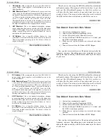
– This switch engages the tube simulation circuitry for the
MicroBassII. In difference from the Drive circuitry this simulator is static
and works only on fairly high levels, giving a soft clip limiting effect.
__________________________________________________________
EFFECTS LOOP
– EBS MicroBassII is provided with an effect loop for
the use of external units such as box or rack effects.
FX MIX
- Controls the amount of effect, all from 0% up to 100%. When
set to 100%, the effects loop is purely serial, and when the effects blend is
50%, the effects loop works in parallel mode.
The effect loop is put before the balanced output, so the effect signal will
be present at the balanced output.
__________________________________________________________
T
HE
C
ONTROL
S
WITCHES
:
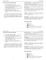
There are two footswitches for rapidly changing the state of the EBS
MicroBassII:
A/B
: Selects active channel A or B. It the Mode switch on channel B is
set to A+B, this switch selects channel A active or channel A
AND
B.
When using both inputs and the A+B mode is selected, you have the A
and B mix mode selected, so then this switch has no effect and no channel
LED will light.
MUTE
: Mutes the Output, Headphones output and Balanced Output.
This is useful when changing instruments or when tuning. The Link
output from channel A is not muted with this switch.
U
SING
T
WO
I
NSTRUMENTS
M
ODE
:
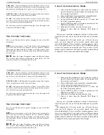
1) Connect the first instrument to input A and the second to
input B. Normally you would connect the instrument with
lowest output to channel A.
2) Connect the Output to power amplifier or amplifier head.
3) Set the A/B switch so that Channel A is active.
4) Set the BASS and TREBLE controls to 12 o’clock and
the GAIN to minimum position.
5) Set the DRIVE control to minimum position and the
MIDDLE and EDGE to 12 o’clock.
6) Make sure all switches are in the outer position.
7) Connect to mixer from the Balanced XLR Output if
required.
You may now switch the instruments with the A/B foot switch.
Adjust the gain and EQ on the individual channels for personal
taste.
By engaging the A+B mode switch you will enter the mix
mode, and both channels will be mixed equally rather than
selected individually. This is useful for teaching purposes, but is
also a very good feature if you wish to mix two different pickup
systems, for example on an upright bass. Here is where a piezo
pickup would be connected to channel A, and the standard pickup
to channel B. In this mode no channel LED will light.
C
OMMON
F
EATURES
G
ETTING
S
TARTED
12 5
TUBE SIM.
– This switch engages the tube simulation circuitry for the
MicroBassII. In difference from the Drive circuitry this simulator is static
and works only on fairly high levels, giving a soft clip limiting effect.
__________________________________________________________
EFFECTS LOOP
– EBS MicroBassII is provided with an effect loop for
the use of external units such as box or rack effects.
FX MIX
- Controls the amount of effect, all from 0% up to 100%. When
set to 100%, the effects loop is purely serial, and when the effects blend is
50%, the effects loop works in parallel mode.
The effect loop is put before the balanced output, so the effect signal will
be present at the balanced output.
__________________________________________________________
T
HE
C
ONTROL
S
WITCHES
:
There are two footswitches for rapidly changing the state of the EBS
MicroBassII:
A/B
: Selects active channel A or B. It the Mode switch on channel B is
set to A+B, this switch selects channel A active or channel A
AND
B.
When using both inputs and the A+B mode is selected, you have the A
and B mix mode selected, so then this switch has no effect and no channel
LED will light.
MUTE
: Mutes the Output, Headphones output and Balanced Output.
This is useful when changing instruments or when tuning. The Link
output from channel A is not muted with this switch.
U
SING
T
WO
I
NSTRUMENTS
M
ODE
:
1) Connect the first instrument to input A and the second to
input B. Normally you would connect the instrument with
lowest output to channel A.
2) Connect the Output to power amplifier or amplifier head.
3) Set the A/B switch so that Channel A is active.
4) Set the BASS and TREBLE controls to 12 o’clock and
the GAIN to minimum position.
5) Set the DRIVE control to minimum position and the
MIDDLE and EDGE to 12 o’clock.
6) Make sure all switches are in the outer position.
7) Connect to mixer from the Balanced XLR Output if
required.
You may now switch the instruments with the A/B foot switch.
Adjust the gain and EQ on the individual channels for personal
taste.
By engaging the A+B mode switch you will enter the mix
mode, and both channels will be mixed equally rather than
selected individually. This is useful for teaching purposes, but is
also a very good feature if you wish to mix two different pickup
systems, for example on an upright bass. Here is where a piezo
pickup would be connected to channel A, and the standard pickup
to channel B. In this mode no channel LED will light.


