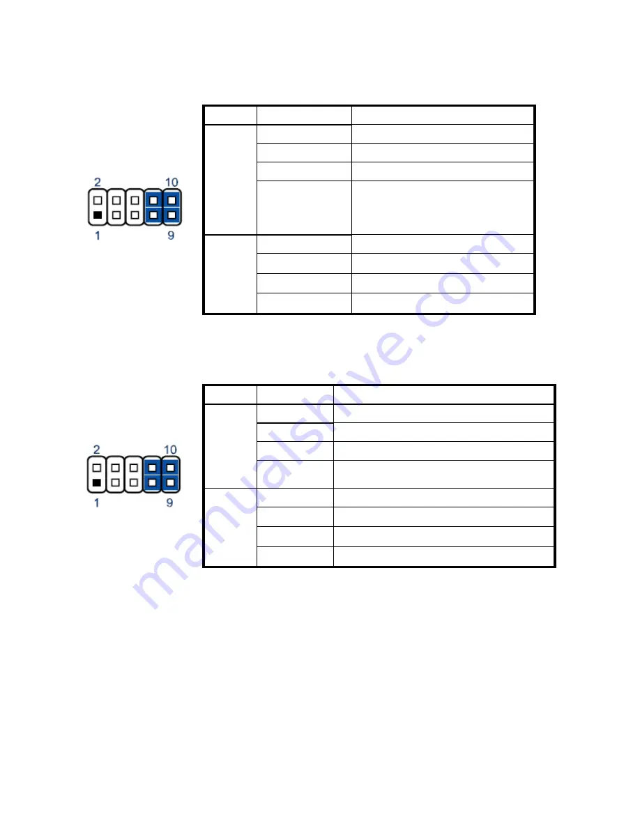
JP4 COM 1 Power COM1 Signal / Power Selection
Jumper
Setting
Function
1-3 Short
Pin 1 of COM1 = +12V
3-5 Short
Pin 1 of COM1 = +5V
5-7 Short
Pin 1 of COM1 = +5V
1
Pin 1 of COM1 = DCD@RS232,
TX-@RS422, DATA-@RS485
(Default)
7-9 Short
2-4 Short
Pin 9 of COM1 = +12V
4-6 Short
Pin 9 of COM1 = +5V
6-8 Short
Pin 9 of COM1 = +5V
2
8-10 Short
Pin 9 of COM1 = RI (Default)
Pitch: 2.54mm [YIMTEX 3322*05SAGR(6T]
JP5/ 6/ 7 COM2/ 3/ 4 Signal / Power Selection
Jumper
Setting
Function
1-3 Short
Pin 1 of COM2/ 3/ 4 = +12V
3-5 Short
Pin 1 of COM2/ 3/ 4 = +5V
5-7 Short
Pin 1 of COM2/ 3/ 4 = +5V
1
7-9 Short
Pin 1 of COM2/ 3/ 4 = DCD (Default)
2-4 Short
Pin 9 of COM2/ 3/ 4 = +12V
4-6 Short
Pin 9 of COM2/ 3/ 4 = +5V
6-8 Short
Pin 9 of COM2/ 3/ 4 = +5V
2
8-10 Short Pin 9 of COM2/ 3/ 4 = RI (Default)
Pitch: 2.54mm [YIMTEX 3322*05SAGR(6T]
For the location of JP4/5/6/7 on the main board, please see the figure below:
Chapter 6
37
Summary of Contents for BPC65-B-A16G
Page 1: ...User s Manual BPC65 B A16G...
Page 6: ...7 2 The Wall Mount Kit 42 7 3 Build in Dimension 43 v Contents...
Page 13: ...3 Click Next 4 Read the License Agreement carefully and click Yes 4 Click Next Chapter 3 7...
Page 22: ...7 Click Next 8 Click Next 9 Click Next Chapter 3 16...
Page 44: ...Chapter 6 38...
Page 47: ...7 7 Specification 7 1 The Device Chapter 7 41...


