


Operating and Maintenance Instructions
210-OMI10878
ORIGINAL INSTRUCTIONS
Page 3 of 6
ebm-papst UK Ltd
Chelmsford Business Park Chelmsford Essex CM2 5EZ
Telephone: +44(0)1245468555 Fax: +44(0)1245466336
e-mail
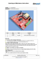
Installation and Connection Details
Note
:
Open Drain Alarm Output
: Connect the alarm output to the input of the monitoring device then connect a pull-up
resistor (typically 100KΩ) between this connection and the supply voltage of the monitoring device. During
normal operation the alarm output will be 0 volts. In an alarm condition the output will be the same as the supply
voltage of the monitoring device.
Relay Alarm Output
: This is a volt free contact that is held closed during normal operation and opens when an
alarm condition is detected.
Temperature sensor
: The 0 volt wire of the sensor must only be connected to the terminal provided on the
controller and not to any other 0 volt source.
Fan Supply
: The fan must be only by connected to the terminals provided on the controller or it will not be able to
monitor and regulate the fan speed correctly.
Operation
Fan speed is controlled according to the selected profile, as shown in the chart opposite.
The fan will run at approximately 15% of maximum speed below the minimum temperature and increase
to 100% at the maximum temperature. If preferred, DIP switch 4 can be used to switch the fan off below the set
point.
If the voltage input limit to the controller or the current output limit to the fan is exceeded, the controller and fan
will switch off to prevent risk of damage and an alarm indication is given.
A yellow LED flashes during normal operation. A blue LED indicates an alarm condition.
DIP Switch Settings
Dip Switch
OFF
ON
1
Profile 2: 35°C to 55°C
Profile1: 20
°C to 40°C
2
Not Used
Not Used
3
Not Used
Not Used
4
15% fan speed at minimum set point
Fan off at minimum set point
5
Soft start on
Soft start off