background image

EGO

EN

10

www.eberg.eu

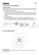
2. INSTALLATION AND OPERATION

TOUCH CONTROL PANEL

FAN INSTALLATION

The base of the fan is a plastic disc with a round hole in the center. The base consists of two  

elements (semicircles) that must be connected with each other. The plastic nut for attaching the 

base is originally attached to the fan.

1.  First, unscrew the nut for fixing the base from the fan.

2.  In the next step, place the round base on the bottom of the fan, and then attach it with the 

previously removed plastic cap. Remember to route the power cord through the center of 

the round hole in the base and lead it out of the base perimeter through a special hole on 

the edge.

3.  Then tighten the nut. 

4.  After mounting the base, place the fan in the correct (vertical) position on the base.

5.  Then connect the device to the power source. When connected to the power supply, the 

device will go into standby mode, the STAND BY indicator will light up on the display.

ON / OFF button

Pressing the „ON / OFF” button will start the device, pressing this button again will put the fan  

in standby mode.

Summary of Contents for EGO

Page 1: ...Instrukcja obsługi Instruction manual EGO WENTYLATOR KOLUMNOWY ...

Page 2: ...zczenia należy używać jedynie wilgotnej szmatki z naturalnymi detergentami Nie spłukiwać urządzenia wodą Urządzenia należy używać w dobrze wentylowanym pomieszczeniu Niewolnowkładaćpalco waniżadnychprzedmioto wdowlotu wylotupowietrza poniewaz moz e to prowadzic do poraz enia pra dem lub poz aru i moz e spowodowac uszkodzenie urza dzenia Aby unikna c ryzyka poz aru nie blokuj kratek ani nie manipul...

Page 3: ...a wentylatora zawsze należy odłączyć przewód zasilający Nie należy podłączać urza dzenia do zasilania sieciowego nie mając pewności z e jest prawidłowo zmontowany i ustawiony Nie wolno używać wentylatora z zewnętrznym sterownikiem lub innym urza dzeniem zewne trznym kto re aktywuje urza dzenie automatycznie gdyż istnieje ryzyko wystąpienia poz aru jes li wentylator jest zakryty lub nieprawidłowo u...

Page 4: ...astępnie przymocować ją za pomocą zdemontowanej wcześniej plastikowej nakrętki Należy pamiętać aby przewód zasilania przeprowadzić przez środek okrągłego otworu w podstawie i wyprowadzić poza obwód podstawy przez specjalny otwór 3 Następnie należy dokręcić tę nakrętkę 4 Po zamontowaniu podstawy należy postawić wentylator w prawidłowej pozycji pionowej na podstawie Zwrócić szczególna uwagę na prowa...

Page 5: ...tor będzie pracował jak w trybie NATURALNYM na prędkości 3 WYSOKA przez następne pół godziny będzie pracował jak w trybie NATURALNYM na prędkości 2 ŚREDNIA a następnie po upływie tego czasu będzie pracował jak w trybie NATURALNYM na prędkości 1 NISKA Tryb SLEEP prędkość 2 ŚREDNIA Przez pierwsze pół godziny wentylator będzie pracował jak w trybie NATURALNYM na prędkości 2 ŚREDNIA a następnie po upł...

Page 6: ... musi być skierowany w stronę odbiornika wentylatora Odbiornik znajduje się z przodu obudowy wentylatora 3 Normalny zasięg pilota to około 6 metrów od frontu urządzenia oraz pod kątem nie przekraczającym 30 4 Należy unikać bezpośredniego promieniowania światła słonecznego na odbiornik aby nie zakłócać poprawnego działania pilota 5 Należy bezpiecznie przechowywać pilot aby uniknąć upadku i uderzeń ...

Page 7: ...YSZCZENIE I KONSERWACJA 4 AKCESORIA W ZESTAWIE 5 DANE TECHNICZNE 6 UTYLIZACJA INFORMACJE DOTYCZĄCE PRAWIDŁOWEGO USUWANIA PRODUKTU ZGODNIE Z DYREKTYWĄ EUROPEJSKĄ 2002 96 WE Gdy urządzenie osiągnie koniec okresu użytkowania nie wolno go wyrzucać razem z odpadami domowymi Aby chronić nasze środowisko i maksymalnie przetwarzać wykorzystane surowce urządzenie musi być dostarczone do właściwego zakładu ...

Page 8: ...is may result in electric shock or fire and may damage the device To avoid the risk of fire do not block the grilles or manipulate them in any way during fan operation Do not use the device if the cord or plug is damaged If the power cord is damaged it should be replaced by the manufacturer dealer or a qualified person in order to avoid a hazard The device must not be used if it has been overturne...

Page 9: ...evice that activates the device automatically as there is a risk of fire if the fan is covered or placed incorrectly Do not run the cable under carpets Do not cover the power cord with blankets carpets or similar materials Place the cord far away from busy places or where it cannot be accidentally pulled out Do not use the fan near bathtubs showers washbasins swimming pools etc Do not use the devi...

Page 10: ...m of the fan and then attach it with the previously removed plastic cap Remember to route the power cord through the center of the round hole in the base and lead it out of the base perimeter through a special hole on the edge 3 Then tighten the nut 4 After mounting the base place the fan in the correct vertical position on the base 5 Then connect the device to the power source When connected to t...

Page 11: ...he first half hour the fan will work as in NATURAL mode at speed 3 HIGH for the next half hour it will work as in NATURAL mode at speed 2 MEDIUM and then after that time it will work as in NATURAL mode at speed 1 LOW SLEEP mode speed 2 MEDIUM For the first half hour the fan will work as in NATURAL mode at speed 2 MEDIUM and t h e n after that time it will work as in NATURAL mode at speed 1 LOW SLE...

Page 12: ...ed on the front of the housing 3 The normal range of the remote control is about 6 meters from the front of the device and at an angle not exceeding 30 4 Avoid direct sunlight on the receiver to avoid interfering with the remote control 5 Store the remote control securely to avoid falling and bumps 6 When it is necessary to replace the battery remove the battery from the compartment located at the...

Page 13: ...UDED 5 TECHNICAL SPECIFICATION 6 DISPOSAL INFORMATION ON CORRECT DISPOSAL OF THE PRODUCT IN ACCORDANCE WITH EUROPEAN DIRECTIVE 2002 96 EC After the end of the device s service life it must not be disposed of as unsorted municipal waste To protect the environment and process the raw materials as much as possible the device must be delivered to the appropriate waste disposal plant or organization th...

Page 14: ...ntacji Technicznej 5 Stwierdzone uszkodzenia urządzenia objętego Gwarancją należy zgłosić Climateo eu Sp z o o Kokotów 703 32 002 Kokotów tel 48 513 677 545 www eberg eu 6 Zgłoszenie reklamacyjne powinno zawierać 1 Model urządzenia 2 Numer seryjny 3 Datę zgłoszenia reklamacji 4 Opis uszkodzenia 5 Datę zakupu 6 Kopię dowodu zakupu 7 Zgłoszenia reklamacyjne będą rozpatrzone w terminie nie dłuższym n...

Page 15: ...fabr nr silnika Nr rachunku faktury Data sprzedaży KARTA GWARANCYJNA Nazwa i adres firmy Telefon kontaktowy Osoba do kontaktu Dane zgłaszającego reklamację Adnotacje o przebiegu napraw Data zgłoszenia Data naprawy Uszkodzenie Rodzaj naprawy Wykonał serwis podpis i pieczęć ...

Page 16: ...Climateo eu Sp z o o Kokotów 703 32 002 Kokotów biuro eberg eu tel 48 513 677 545 www eberg eu ...

Reviews: