Design of the XC100
10/10 MN05003004Z-EN
14
CANopen interface
The CPUs can be connected to the CANopen bus via the electrically
isolated ISO-11898 interface.
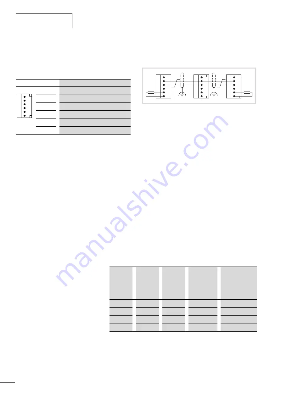
The connector has the following assignment:
The CPUs can be operated on the CAN bus either as the network
(NMT) master or as the NMT slave.
The CPU can be used to send/receive CAN telegrams directly
to/from the user program. An interruption on the CAN Bus will
only be recognised when the respective CAN slave is monitored by
the PLC (Nodeguarding function).
Power supply
The sequence in which the power supply of the individual CAN
slaves is connected does not have an effect on the functionality of
the CAN bus. Depending on the parametric programming, the PLC
“waits” for the non-existent slave or starts it at the time at which
the slave is interfaced to the CAN network.
Start/Stop behaviour
If you set the operating mode selector to the “Stop” position, all
outputs of the decentralized devices will be set to the “0” level.
Bus terminating resistors
The ends of the network link must be terminated with 120
O
bus
termination resistors:
Terminals 1 and 4, 2 and 5, 3 and 6 are internally connected.
Properties of the CANopen cable
Use only cable approved for CANopen applications and with the
following characteristics:
• Characteristic impedance 100 to 120
O
• Capacitance < 60 pF/m
The demands placed on the cable, connectors and bus termination
resistors are specified in ISO 11898. Following you will find some
demands and stipulations listed for the CANopen network.
In the following table, standard parameters for the CANopen
network with less than 64 CANopen slaves are listed (table
complies with the stipulations of the ISO 11898).
Table 2:
Standard parameters for CANopen network cable according to
the ISO 11898
The length of the CANopen bus cable is dependant on the
conductor cross-section and the number of bus users connected.
The following table includes values for the bus length in
dependance on the cross-section and the connected bus users,
which guarantee a secure bus connection (table corresponds with
the stipulations of the ISO 11898).
Terminal
Signal
6
GND
5
CAN_L
4
CAN_H
3
GND
2
CAN_L
1
CAN_H
Connector type: 6-pole, plug-in spring-loaded terminal block, conductor
cross-section up to 0.5 mm
2
6
5
4
3
2
1
Figure 14: Possible configuration of a CANopen bus with bus
termination resistors
6
5
4
3
2
1
6
5
4
3
2
1
6
5
4
3
2
1
CAN_L
CAN_H
120
O
120
O
Bus length
[m]
Loop
resistance
[m
O
/m]
Conductor
cross-
section
[mm
2
]
Bus
termination
resistor
[
O
]
Transfer rate
with cable length
[kBit/s]
0 – 40
70
0.25 – 0.34
124
1000 at 40 m
40 – 300
< 60
0.34 – 0.6
150 – 300
> 500 at 100 m
300 – 600
< 40
0.5 – 0.6
150 – 300
> 100 at 500 m
600 – 1000
< 26
0.75 – 0.8
150 – 300
> 50 at 1000 m
Summary of Contents for XC200 Series
Page 4: ...II ...
Page 8: ...10 10 MN05003004Z EN 4 ...
Page 28: ...10 10 MN05003004Z EN 24 ...
Page 50: ...10 10 MN05003004Z EN 46 ...
Page 74: ...10 10 MN05003004Z EN 70 ...


