background image


65A7355H01  November 2011   www.eaton.com 


1 Safety 

W-VAC

i

 vacuum circuit breakers are equipped with 

high speed, high energy operating mechanisms. They 
are designed with several built-in interlocks and safety 
features to provide safe and proper operating 
sequences. 
 

1.1 

Safety precautions 

All safety codes, safety standards and/or regulations 
must be strictly observed in the installation, operation 
and inspection of this device. 
 

  WARNING 

WARNING indicates a hazard with a medium 
level of risk which, if not avoided, may result in 
death or serious bodily injury 


  CAUTION 

CAUTION indicates a hazard with a low level of risk 
which, if not avoided, could result in minor or 
moderate injury or property damage only. 


1.2 

Safety practices 


  WARNING 

To protect the personnel associated with 
installation, operation, and inspection of these 
breakers, the following practices must be 
followed: 


As defined in the local electrical code, only 
qualified persons who are familiar with the 
installation and Inspection of medium voltage 
circuits and equipment should be permitted to 
work on these breakers. 


Read these instructions carefully before 
attempting any installation, operation or inspection 
of these breakers. 


Always remove the withdrawable breakers from 
their enclosures before performing any inspection. 
Failure to do so could result in electrical shock 
leading to death, severe personal injury or 
property damage. 


Do not work on a breaker with the secondary test 
coupler engaged or fixed secondary connections 
made. Failure to disconnect the test coupler could 
result in an electrical shock leading to death, 
personal injury or property damage. 


Do not work on a closed breaker or a breaker with 
closing springs charged. The closing spring should 
be discharged and the main contacts open before 
working on the breaker. Failure to do so could 
result in cutting or crushing injuries. 


Do not use a withdrawable circuit breaker by itself 
as the only mean of isolating a high voltage circuit, 
remove the circuit breaker to the DISCONNECT 
POSITION and follow correct lock-out and tagging 

rules, as well as all applicable codes, regulations 
and work rules. 


Do not leave a withdrawable circuit breaker in an 
intermediate position in the cell. Always have the 
circuit breaker either in the “Test” or “Service” 
position. Failure to do so could result in a flash 
over, death, personal injury or property damage. 


Always re-insert the handle into the front panel of 
the breaker after charging the closing springs. 
Otherwise the circuit breaker will not operate. 


Circuit breaker elements are equipped with safety 
interlocks. DO NOT remove, interfere with or in 
any manner defeat the safety interlocks. This may 
result in death, bodily injury or equipment damage. 


All personnel involved in operations carried out on, 
with or near electrical installations, require to have 
been instructed on the safety requirements, safety 
rules and instructions applicable to the operation 
of the installation. 


Ensure that access and escape routes are free at 
all times. Do not leave flammable materials in or 
near access and escape routes.  


Flammable materials must not be stored in areas 
which could be affected by arcs, such as: ethers, 
alcohols and alcohol based cleaners. In the event 
of a fire, never attempt to extinguish a fire on the 
switchgear unit before it is completely dead; this 
applies to both primary and secondary switchgear. 
Even if non-conducting extinguishing materials are 
used, electricity may pass through the 
extinguishing equipment. Never extinguish a fire 
on the unit with water. 


  WARNING 

The circuit breaker elements described in this 
book are designed and tested to operate within 
their nameplate ratings. 

Operation outside of these ratings may cause 
the equipment to fail, resulting in death, bodily 
injury and property damage. 

These circuit breaker elements are designed to 
be installed pursuant to the iec standards.  
Serious injury, including death, can result from 
failure to follow the procedures outlined in this 
manual.  These circuit breaker elements are sold 
pursuant to a non-standard purchasing 
agreement which limits the liability of the 
manufactor. 


Summary of Contents for W-VACi

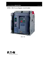
Page 1: ...User manual W VACi W VACi 12 17 5 24 kV IEC Vacuum Circuit Breakers...

Page 2: ...2 65A7355H01 November 2011 www eaton com...

Page 3: ...eights 37 3 6 Photographic Description 38 4 Inspection 40 4 1 Inspection 40 4 2 Frequency of Inspection 40 4 3 Inspection Process 40 4 4 Vacuum Interrupter Integrity Test 40 4 5 Insulation Inspection...

Page 4: ...ning 52 6 7 Control Schemes 52 6 8 Selective Parts Configuration 52 7 Renewal parts 64 7 1 General 64 7 2 Ordering Instructions 64 7 3 Standard accessories 64 7 4 Optional accessories 67 8 Appendix 69...

Page 5: ...age circuit remove the circuit breaker to the DISCONNECT POSITION and follow correct lock out and tagging rules as well as all applicable codes regulations and work rules Do not leave a withdrawable c...

Page 6: ...s the IEC 62271 1 standard One factor that is not hindered by this property is the internal insulation of the vacuum interrupters 2 3 Technology Parameters Charts on the following pages include all te...

Page 7: ...40 60 40 60 40 60 40 60 40 60 40 60 40 60 40 60 Closing Speed1 m s 0 7 1 3 0 7 1 3 0 7 1 3 0 7 1 3 0 7 1 3 0 7 1 3 0 7 1 3 0 7 1 3 0 7 1 3 0 7 1 3 0 7 1 3 0 7 1 3 Opening Speed1 m s 1 0 1 7 1 0 1 7 1...

Page 8: ...60 40 60 40 60 40 60 Closing Speed1 m s 0 7 1 3 0 7 1 3 0 7 1 3 0 7 1 3 0 7 1 3 0 7 1 3 0 7 1 3 0 7 1 3 0 7 1 3 0 7 1 3 Opening Speed1 m s 1 0 1 7 1 0 1 7 1 0 1 7 1 0 1 7 1 0 1 7 1 0 1 7 1 0 1 7 1 0...

Page 9: ...40 60 40 60 40 60 40 60 40 60 Closing Speed1 m s 0 7 1 3 0 7 1 3 0 7 1 3 0 7 1 3 0 7 1 3 0 7 1 3 Opening Speed1 m s 1 0 1 7 1 0 1 7 1 0 1 7 1 0 1 7 1 0 1 7 1 0 1 7 D C Component of Breaking Current Id...

Page 10: ...60 40 60 40 60 Closing Speed1 m s 0 7 1 3 0 7 1 3 0 7 1 3 0 7 1 3 0 7 1 3 0 7 1 3 0 7 1 3 0 7 1 3 0 7 1 3 0 7 1 3 Opening Speed1 m s 1 0 1 7 1 0 1 7 1 0 1 7 1 0 1 7 1 0 1 7 1 0 1 7 1 0 1 7 1 0 1 7 1...

Page 11: ...0 25 50 Opening Time ms 40 60 40 60 40 60 40 60 40 60 Closing Speed 1 m s 0 7 1 3 0 7 1 3 0 7 1 3 0 7 1 3 0 7 1 3 Opening Speed1 m s 1 0 1 7 1 0 1 7 1 0 1 7 1 0 1 7 1 0 1 7 D C Component of Breaking C...

Page 12: ...ltitude Do not exceed 1000m For applications above 1000 m de rating is required Service Site The environment shall be free of water flame and or explosive hazard No chemical corrosive gases and or int...

Page 13: ...F 3 27 2000 31 5 210 310 12W 3 16 12F 3 27 3150 31 5 275 310 12W 4 17 12F 4 28 1250 40 210 310 12W 3 16 12F 3 27 1600 40 210 310 12W 3 16 12F 3 27 2000 40 210 310 12W 3 16 12F 3 27 3150 40 275 310 12W...

Page 14: ...November 2011 www eaton com All Dimensions are in millimeters Fig 2 2 12kV Withdrawable W VACi Circuit Breaker Frame 12W 1 Applicable Ratings Voltage Breaking Current Normal Current 12kV 25kA 630A 12k...

Page 15: ...ton com 15 All Dimensions are in millimeters Fig 2 3 12kV Withdrawable W VACi Circuit Breaker Frame 12W 2 Applicable Ratings Voltage Breaking Current Normal Current 12kV 25kA 630A 800A NA 26 3kA 630A...

Page 16: ...ithdrawable W VACi Circuit Breaker Frame 12W 3 Applicable Ratings Voltage Breaking Current Normal Current 12kV 25kA NA 1600A 1 2000A 2 26 3kA NA 1600A 1 2000A 2 31 5kA NA 1600A 1 2000A 2 40kA 1250A 1...

Page 17: ...ww eaton com 17 Figure 2 5 12kV Withdrawable W VACi Circuit Breaker Frame 12W 4 Applicable Ratings Voltage Breaking Current Normal Current 12kV 25kA 3150A 26 3kA 3150A 31 5kA 3150A 40kA 3150A 2 These...

Page 18: ...5H01 November 2011 www eaton com All Dimensions are in millimeters Fig 2 6 17 5 kV Withdrawable W VACi Circuit Breaker Frame 17 5W 1 Applicable Ratings Voltage Breaking Current Normal Current 17 5kV 2...

Page 19: ...www eaton com 19 All Dimensions are in millimeters Fig 2 7 17 5 kV Withdrawable W VACi Circuit Breaker Frame 17 5W 2 Applicable Ratings Voltage Breaking Current Normal Current 17 5kV 25kA 630A 800A N...

Page 20: ...2 8 17 5 kV Withdrawable W VACi Circuit Breaker Frame 17 5W 3 Applicable Ratings Voltage Breaking Current Normal Current 17 5kV 25kA NA 1600A 1 2000A 2 31 5kA NA 1600A 1 2000A 2 40kA 1250A 1 1600A 1 2...

Page 21: ...1 www eaton com 21 Figure 2 9 17 5kV Withdrawable W VACi Circuit Breaker Frame 17 5W 4 Applicable Ratings Voltage Breaking Current Normal Current 17 5kV 25kA 3150A 31 5kA 3150A 40kA 3150A 2 These rati...

Page 22: ...1 November 2011 www eaton com All Dimensions are in millimeters Fig 2 10 24 kV Withdrawable W VACi Circuit Breaker Frame 24W 1 Applicable Ratings Voltage Breaking Current Normal Current 24kV 20kA 800A...

Page 23: ...ensions are in millimeters Fig 2 11 24 kV Withdrawable W VACi Circuit Breaker Frame 24W 2 Applicable Ratings Voltage Breaking Current Normal Current 24kV 25kA 1600A 1 2000A 2 1 These ratings do not us...

Page 24: ...355H01 November 2011 www eaton com All Dimensions are in millimeters Fig 2 12 24 kV Withdrawable W VACi Circuit Breaker Frame 24W 3 Applicable Ratings Voltage Breaking Current Normal Current 24kV 25kA...

Page 25: ...01 November 2011 www eaton com 25 All Dimensions are in millimeters Fig 2 13 12kV Fixed W VACi Circuit Breaker Frame 12F 1 Applicable Ratings Voltage Breaking Current Normal Current 12kV 25kA 630A 26...

Page 26: ...www eaton com All Dimensions are in millimeters Fig 2 14 12kV Fixed W VACi Circuit Breaker Frame 12F 2 Applicable Ratings Voltage Breaking Current Normal Current 12kV 25kA 630A 800A NA 26 3kA 630A 800...

Page 27: ...kV Fixed W VACi Circuit Breaker Frame 12F 3 Applicable Ratings Voltage Breaking Current Normal Current 12kV 25kA NA 1600A 1 2000A 2 26 3kA NA 1600A 1 2000A 2 31 5kA NA 1600A 1 2000A 2 40kA 1250A 1 160...

Page 28: ...2011 www eaton com Fig 2 16 12kV Fixed W VACi Circuit Breaker Frame 12F 4 Applicable Ratings Voltage Breaking Current Normal Current 12kV 25kA 3150A 26 3kA 3150A 31 5kA 3150A 40kA 3150A 2 These ratin...

Page 29: ...55H01 November 2011 www eaton com 29 All Dimensions are in millimeters Fig 2 17 17 5kV Fixed W VACi Circuit Breaker Frame 17 5F 1 Applicable Ratings Voltage Breaking Current Normal Current 17 5kV 25kA...

Page 30: ...r 2011 www eaton com All Dimensions are in millimeters Fig 2 18 17 5kV Fixed W VACi Circuit Breaker Frame 17 5F 2 Applicable Ratings Voltage Breaking Current Normal Current 17 5kV 25kA 630A 800A NA 31...

Page 31: ...ig 2 19 17 5kV Fixed W VACi Circuit Breaker Frame 17 5F 3 Applicable Ratings Voltage Breaking Current Normal Current 17 5kV 25kA NA 1600A 1 2000A 2 31 5kA NA 1600A 1 2000A 2 40kA 1250A 1 1600A 1 2000A...

Page 32: ...mber 2011 www eaton com Fig 2 20 17 5kV Fixed W VACi Circuit Breaker Frame 17 5F 4 Applicable Ratings Voltage Breaking Current Normal Current 17 5kV 25kA 3150A 31 5kA 3150A 40kA 3150A 2 These ratings...

Page 33: ...01 November 2011 www eaton com 33 All Dimensions are in millimeters Fig 2 21 24kV Fixed W VACi Circuit Breaker Frame 24F 1 Applicable Ratings Voltage Breaking Current Normal Current 24kV 20kA 800A 20k...

Page 34: ...Dimensions are in millimeters Fig 2 22 24kV Fixed W VACi Circuit Breaker Frame 24F 2 Applicable Ratings Voltage Breaking Current Normal Current 24kV 25kA 1600A 1 2000A 2 1 These ratings do not use a...

Page 35: ...7355H01 November 2011 www eaton com 35 All Dimensions are in millimeters Fig 2 23 24kV Fixed W VACi Circuit Breaker Frame 24F 3 Applicable Ratings Voltage Breaking Current Normal Current 24kV 25kA 250...

Page 36: ...d be returned to its original shipping container until it is ready to be installed When a circuit breaker is ready for installation a removable lifting bar in conjunction with an overhead lifter or po...

Page 37: ...gear 3 5 W VACi Circuit Breaker Weights Table 3 1 12kV Circuit Breaker weights 12 kV Circuit Breaker Weights kg 630A 800A 1250A 1600A 2000A Fixed 25kA 83 83 92 130 130 26 3kA 83 83 92 130 130 31 5kA 9...

Page 38: ...Charged Discharged Indicator 5 Manual Open Button 11 Operation Counter 6 Racking in Assembly 12 Coupling Lever for Racking in and out Fig 3 4 Internal view of W VACi Circuit Breaker Element 1 Universa...

Page 39: ...ker W VACi with210 mm Pole Spacing Breaker W VACi with275 mm Pole Spacing Breaker Fig 3 5 W VACi Circuit Breaker Withdrawable Frames Fig 3 6 Typical Rear View of a Withdrawable W VACi Finger Cluster R...

Page 40: ...f these parameters can be readily checked by a one minute AC high potential test During this test the following warning must be observed Table 4 1 Testing Ratings Breaker Testing Voltage 12kV 28kV ac...

Page 41: ...ircuit resistance DO NOT directly clamp onto the springs when injecting current When testing circuit resistance clamp directly onto the finger cluster between the springs as shown Fig 4 1 Finger Clust...

Page 42: ...nnects No burning or damage or spring discoloration Visual inspection Replace if burned damaged eroded or discolored Control Circuit Parts Shunt Closing and Opening release including disconnects Smoot...

Page 43: ...ied Secondary disconnects is not in service Anti pumping device is in service Shunt closing release failure The breaker is between service and test position when it is in the switchgear Mechanical Int...

Page 44: ...ail to Trip Breaker does not trip Shunt trip release circuit No control power or its voltage is out of range fuse blown or switch off or wrong voltage applied Secondary disconnect is not connected Mec...

Page 45: ...ed 50 N Not following these warnings when pushing the close button could cause the electromagnetic interlock to become damaged and jam the mechanism 5 2 Manual Operation Check Withdraw the charging ha...

Page 46: ...of the cell before inserting or mounting the breaker for excessive dirt or anything that might interfere with the breaker travel or installation WARNING Extreme caution must be exercised to ensure tha...

Page 47: ...ted 2 When the breaker is in the CLOSED state and the function of anti pumping is on the spring release cannot actuate 3 When the breaker is in the CLOSED state it cannot be racked into the switchgear...

Page 48: ...nterlock works with the Eaton W VACi breaker secondary disconnect It is a rod that hooks over the secondary disconnect This prevents the secondary disconnect from coming out of its position when it is...

Page 49: ...ough the VI and through an electrical connection and flows out the other conductor 6 3 Operating Mechanism WARNING Keep hands and fingers away from the breaker s internal parts while the breaker conta...

Page 50: ...rged the indicator will display CHARGED and the motor cutting switch will break the power supply of the charging motor The circuit breaker is now ready for closing 6 5 Closing The closing operation is...

Page 51: ...Open and Closing Spring Charged Fig 6 9 Breaker Closed and Closing Spring Charged 1 Closing Spring 2 Closing Spring Lever 3 Spring Release D Shaft 4 Close Roller 5 Cam 6 Cam Shaft 7 Main Roller 8 Tri...

Page 52: ...it Value Rated Voltage VDC Ua 24 48 60 110 125 220 250 Rated Voltage VAC Ua 110 120 220 230 Voltage Range Ua 85 110 Time for Charging S s 15 Rated Parameters of Releases1 Item Unit Value Rated Voltage...

Page 53: ...65A7355H01 November 2011 www eaton com 53 Fig 6 10 Control Schematic...

Page 54: ...54 65A7355H01 November 2011 www eaton com...

Page 55: ...65A7355H01 November 2011 www eaton com 55 Fig 6 11 Control Schematic...

Page 56: ...56 65A7355H01 November 2011 www eaton com Fig 6 12 Control Schematic...

Page 57: ...65A7355H01 November 2011 www eaton com 57 Fig 6 13 Control Schematic...

Page 58: ...58 65A7355H01 November 2011 www eaton com Fig 6 14 Control Schematic...

Page 59: ...65A7355H01 November 2011 www eaton com 59 Fig 6 15 Control Schematic...

Page 60: ...60 65A7355H01 November 2011 www eaton com Fig 6 16 Control Schematic...

Page 61: ...65A7355H01 November 2011 www eaton com 61 Fig 6 17 Control Schematic...

Page 62: ...62 65A7355H01 November 2011 www eaton com Fig 6 18 Control Schematic...

Page 63: ...65A7355H01 November 2011 www eaton com 63 Fig 6 19 Control Schematic...

Page 64: ...fy the control voltage for electrical components d Specify the method of shipping desired e Send all orders or correspondence to the appropriate Eaton representative 7 3 Standard accessories Table 7 1...

Page 65: ...C 110 120 220 230 V Operating Limits 70 110 Ua DC 85 110 Ua AC Insulating voltage 2000 V 50 60 Hz for 1 min Charging Motor M 40kA and below This device charges the mechanism closing springs electrical...

Page 66: ...aling of the state of the closing spring 24 VDC 4 0A 65A7014G01 48 VDC 2 5A 60 VDC 2 0A 110 125 VDC 0 9A 220 250 VDC 0 4A 110 120 VAC 9 5A 220 230 VAC 5 0A Attributes Insulating voltage 2000 V 50 60 H...

Page 67: ...230 VAC 1 4A 65A7003G12 Attributes Ua DC 24 48 60 110 125 220 250 V Ua AC 110 120 220 230 V Operating Limits 70 110 Ua DC 85 110 Ua AC Insulating voltage 2000 V 50 60 Hz for 1 min Mechanism Electromag...

Page 68: ...m being unsafely operated in the event that the control circuit is not energized 24 VDC 65A7006G01 48 VDC 65A7006G02 60 VDC 65A7006G13 110 125 VDC 65A7006G04 220 250 VDC 65A7006G06 110 120 VAC 65A7006...

Page 69: ...ions at Start ________ List Explanation Result Reference Section 1 Check the parts for any that are damaged loose distortion missing 3 2 2 Operate manually charged close open 4 3 3 Check insulation of...

Page 70: ...48V DC 60V DC 110V DC 125V DC 220V DC 250V DC 110V AC 120V AC 220V AC 230V AC Shunt Closing Release Ua 24V DC 48V DC 60V DC 110V DC 125V DC 220V DC 250V DC 110V AC 120V AC 220V AC 230V AC Charging Mot...

Page 71: ...nced products at the time of issue and may not reflect their future characteristics Eaton Corporation reserves the right to modify the contents of this document and the characteristics of the referenc...

Reviews: