background image

33

Operation

EATON TFX INSTALLATION AND OPERATION MANUAL

   6046279-001   

September 2019

   www.eaton.com

OUTPUT FUNCTION

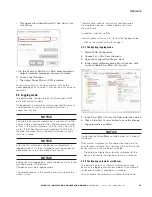
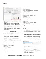
Make the settings for the input function under IO 

m

oDule


C

onfiguration

 > D

igital

 o

utput

 – C

hannel

 6.

1.  Select the object 

D

igital

 o

utput

 – C

hannel


6.

2.  In the 

C

hannel

 C

onfiguration

 list, select the 

configuration ON – OFF 

D

igital

 o

utput

.

3.  Save the changes.

The following variables are available:

Table 33:  Output functions

Variable

Function

C

hannel

 C

onfiguration

Enable and disable the digital output.

B

ehavior


on

 D

eviCe

 s

oftware


s

tatus

 C

hange

Behavior on CANopen mode STOP 

or 

preoperational

. The output can 

retain its current value or be set to a 

defined value.

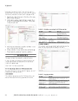
5.6.3  Operation time counter

The device features an internal operation time counter.
The 

o

peration


time


total

 object belongs to the object 

dictionary group 

D

eviCe

 v

ariaBles

 > i/o, s

ensors

, D

iagnosis

.

The operation time counter cannot be reset. The operation 

time counter runs as soon as the device is in standard 

mode (not sleep mode).
For detailed information on creating objects, see chapter 

Creating object dictionary groups and objects.

5.6.4  Power management

The device supports the following power modes:
>  Standard mode
>  Sleep mode (energy saving mode)

NOTICE

The device can only switch to sleep mode when terminal 15 

is disabled (LOW).

In sleep mode, none of the device functions are available.

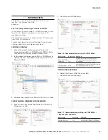
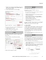
The required variables belong to the object dictionary group 

D

eviCe

 v

ariaBles

 > p

ower

 m

anagement

.

You can enable sleep mode as follows.
>  Enabling sleep mode after a set time period: 

p

ower

 m

anagement

 – C

an

 s

leep

 t

ime

>  Monitoring terminal 15. As soon as the device registers 

LOW on terminal 15, a delay time is enabled. If timeout is 

reached before the device detects HIGH on terminal 15, 

the device goes into sleep mode: 

p

ower

 m

anagement

 - s

hutDown

 D

elay

 t

ime

If the device detects HIGH on terminal 15 or a CAN message 

while in sleep mode, it switches to standard mode (wake-up).

NOTICE

The device can only be woken from sleep mode into 

standard mode by CAN1 messages. CAN2 messages are 

not available with the current product offering

You can configure additional flags that switch the device to 

standard mode.
>  Wake-up after a defined time: 

p

ower

 m

anagement

 - C

yCliC

 w

ake

-u

p

 t

ime

>  Wake-up due to vibration. You can set the intensity of 

the vibration: 

p

ower

 m

anagement

 - a

CCeleration

 s

ensor

 w

ake

-

up

 f

orCe

For detailed information on creating objects, see chapter 

Creating object dictionary groups and objects.

5.6.5  Geofence

GEOFENCE MODE

The device features a geofence monitoring function. This 

allows you to monitor whether the device is located inside 

or outside a pre-defined fence and when the device crosses 

the fence.
There are three ways to define the fence:
>  Define center and radius of a circle. The center of the 

circle is defined as a fixed point.

>  Define center and radius of a circle. The current position 

on enabling the function is used as the center of 

the circle.

>  Two opposite points are defined for a rectangle.
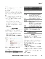
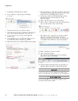
The variables belong to the object dictionary group 

D

eviCe


v

ariaBles

 > i

nternal

 g

eofenCe

.

Summary of Contents for TFX Series

Page 1: ...TFX Installation and Operation Manual...

Page 2: ...special indirect incidental or consequential damage or loss whatsoever including but not limited to damage or loss of use of equipment plant or power system cost of capital loss of power additional e...

Page 3: ...non observance Measures to avoid the danger WARNING Nature and source of the danger Consequences of non observance Measures to avoid the danger CAUTION Nature and source of the danger Consequences of...

Page 4: ...1 4 Conformity 2 1 2 Device functions 2 1 2 1 Available models 2 1 2 2 Scope of supply 3 1 2 3 Kits 3 1 2 4 Software and accessories 3 1 3 Service and support 3 2 0 SAFETY INFORMATION 4 2 1 Safety in...

Page 5: ...cting the device to the Data platform 18 4 6 Mounting the device 18 5 0 OPERATION 20 5 1 Eaton TFX Configurator 20 5 1 1 Creating object dictionary groups and objects 20 5 2 Logging mode 21 5 2 1 Conf...

Page 6: ...on 40 5 10 2 OTAP general process 40 5 10 3 OTAP Recovery Mode 41 5 11 Diagnosis via micro USB port 41 5 12 Factory reset 43 5 12 1 Factory reset via OBW file or CAN 43 5 12 2 Factory reset via the st...

Page 7: ...ATION Not all model variants feature the antenna ports For more information see chapter Available models 1 1 2 Type label The device type label is located on the front of the housing and provides the...

Page 8: ...open the device housing yourself 1 1 4 Conformity For details of the corresponding approval tests see chapter Certification and qualification The device meets the requirements of the following standa...

Page 9: ...02EC77300A 102EC77301A Order number for STARTER KIT 102EC77302A 102EC77302A INFORMATION The HARDWARE KIT only includes the TFX and mounting accessories We recommend that customers without an existing...

Page 10: ...e applicable regulations and precautions for potentially explosive areas Do not mount the antenna in the close proximity of easily ignited substances e g fuel tanks and insufficiently shielded electro...

Page 11: ...100 MHz UMTS FDD 1 band Changes or modifications to this device not expressly approved by the manufacturer can void the user s authority to operate the device under CE rules INFORMATION The horizontal...

Page 12: ...ng mode Yes Yes Input output functions Yes Yes Acceleration sensor Yes Yes Gyro sensor Yes Yes CAN connectors 1 1 GNSS Yes Yes eSIM card Yes Yes 3 1 1 Real time mode In real time mode CAN messages are...

Page 13: ...s an eSIM profile with all the necessary communication settings INFORMATION On delivery the device s eSIM card is not yet enabled After registration of the TFX enabling the eSIM card can take up to 1...

Page 14: ...prox 3 3 V and can supply active antennas with a maximum of 40 mA of power The port is short circuit resistant and recognizes that an antenna is present from a power greater than approx 2 mA CAUTION H...

Page 15: ...When several colors are active simultaneously the LEDs also light up in magenta orange or turquoise The following tables show possible LED indications ON LED The ON LED indicates the power supply stat...

Page 16: ...1 Start cable for main plug connector The cable CLM3 start cable 6 open 2 dsub 1 pw 2 m contained within the Starter Kit features the following connectors and open individual wires 1 micro timer II so...

Page 17: ...eatures a slide switch for a factory reset INFORMATION For more information on how to perform a factory reset see chapter Factory reset via the start cable D sub connector female 9 pin CAN2 Pin Design...

Page 18: ...the device is switched on This activates the MCU internal bootloader 3 4 3 USB connector cable diagnosis The USB cable USB A on micro USB B 1 6 m included in Starter Kit is intended for debugging and...

Page 19: ...malfunction secure the DC power supply circuit with an external 2 A fuse NOTICE Property damage The device must be installed connected and commissioned by a qualified technician Ensure the power suppl...

Page 20: ...ximity of easily ignited substances e g fuel tanks and insufficiently shielded electronic devices CAUTION Health hazards of radio frequency energy Slight or medium injury Make sure the device is switc...

Page 21: ...ttention that the USB plug is correctly aligned to the USB port on the computer before being plugged in and that it is plugged in without using excessive force Incorrect alignment during connection or...

Page 22: ...PC See chapter Connecting the device to the PC 2 Start the EATON Configurator software 3 Click onTools Node Scan in the menu Alternatively you can click on the button in the toolbar 3 3 The Communica...

Page 23: ...ion file available for your specific device it is recommended to create a new device configuration The required object groups and device variables have to be added manually then Refer to Creating obje...

Page 24: ...com and check whether the device is connected to the Data platform If your device does not appear in the machine overview you must activate the device See chapter Activation of the device 4 6 Mounting...

Page 25: ...ositioning 1 Mobile radio antenna 2 GNSS antenna NOTICE Inadequate radio connection The radio connection is influenced by objects or walls Only mount the device in the installation position shown in c...

Page 26: ...ucture of EATON Configurator you can create rename or delete object dictionary groups or objects This chapter explains how to create object dictionary groups and objects The following example shows cr...

Page 27: ...you start logging data check the device status in the machine overview in the Portal The device must be in logging mode The colored squares in the machine overview indicate the current status Constan...

Page 28: ...enable CAN communication and data logging you must configure the following variables CAN VARIABLES The variables required concern the CAN connection and belong to the object dictionary group Device V...

Page 29: ...ain this 2 In the object dictionary group Receive CAN Messages PDOs create a new object dictionary entry Receive Messages PDO 3 Rename the object Receive Message PDO as pgn 61444 RECEIVE MESSAGE COMMU...

Page 30: ...ss These are ignored when the message is received 5 2 3 2 Example 1 Log all data bytes every 60 seconds In this example all data bytes are simply logged cyclically every 60 seconds There are no additi...

Page 31: ...variables belong to the Interface Variables object dictionary group 1 Create the object dictionary group Interface Variables 2 In the INTERFACE VARIABLES object dictionary group create four new Interf...

Page 32: ...ging in PGN 61444 Payload Description Selection Function Log received CAN message Set Log data of the receive CAN message Bytes to log 2 5 and 8 Logging selected data bytes 5 2 3 3 1 Mapping During ma...

Page 33: ...e calculation operations have the following functions Buttons Description C clear deletes the entire calculation operation CE clear entry only deletes the last symbol entered Add variables to the calc...

Page 34: ...le contains position data at least once Enabled Enables disables the position data logging AND OR AND Position data is logged if both conditions time and distance are met OR Position data is logged if...

Page 35: ...3 3 The Create new Job window opens 12 Select the job type Logging 13 Click on the OK button 3 3 The job is added to the Overview list 14 In the CobID field enter the ID hex for the virtual CAN messag...

Page 36: ...chine overview indicate the current status Constant blue device is passive in real time mode Flashing blue device is connected to a real time client software Grayed out device is offline Constant gree...

Page 37: ...transferred to the Data platform you need to take the following steps 1 Check that the object 0x5402 Sub Index 0 has the value 01 This value indicates that PROEMION has transferred a file to the devic...

Page 38: ...roup contains the following variables Table 32 Device variables I O sensors diagnosis Variable Function Operation time total Device operation time in seconds Device Time Unix Format Internal device ti...

Page 39: ...Variables Power Management You can enable sleep mode as follows Enabling sleep mode after a set time period Power Management Can Sleep Time Monitoring terminal 15 As soon as the device registers LOW o...

Page 40: ...end special files to the device via the Data platform to configure or read off variables In the following the files and their structure are described NOTICE Restrictions apply to the file names See ch...

Page 41: ...ers with administrator rights have this authorization INFORMATION If you do not have authorization to perform a configuration update contact the service support See chapter Service and support 1 Start...

Page 42: ...0x1018 0x2 ERROR 0x3337 is not equal to 0xTFX Internal Antenna ABORT CONFIGURATION DOWNLOAD ON ERROR newSW Fw 6 1 0 0 Release newBL Bl 9 1 newDOD CANlink mobile 3337 Demo V1 END 1534329798 5 8 2 CAN...

Page 43: ...the Open button 4 In the Communication Path field select the Connection via Internet n Devices interface from the list 5 Click on the Select Devices button 3 3 The window Select Devices opens 6 If the...

Page 44: ...w 6 1 0 0 Release newBL Bl 9 2 newDOD FOTA Test V4 END 1532700197 Example of protocol content after a failed update BEGIN 1534330801 actSW Fw 6 1 0 0 Release actBL Bl 9 1 actDOD CANlink mobile 3337 De...

Page 45: ...evice restarts automatically 3 3 After the restart the device uses the updated firmware version You can find a tutorial on how to install the firmware to the device in the download area of our website...

Page 46: ...the device uses the updated firmware version You can find a tutorial on how to install the firmware to the device in the download area of our website See also chapter Service and support 5 10 Over the...

Page 47: ...RMATION Before you connect the device to a USB port on your PC install the USB driver packet from Eaton com TFX See chapter Installing software 1 Connect the device to a PC with the USB A to micro USB...

Page 48: ...the menu click on CAN Filter Settings Driver optimized settings Totally open for 11 and 29 bit messages 12 Click on the OK button to save the settings 13 Click on Tools Node Scan in the menu Alternat...

Page 49: ...t to Firmware Defaults Local 0x1011 0x65 The standard configuration of the current firmware is restored All logged data and parameters are deleted The factory configuration is retained INFORMATION You...

Page 50: ...ng plugged in and that it is plugged in without using excessive force Incorrect alignment during connection or the use of excessive force could cause damage to the USB port 1 Connect the device to a P...

Page 51: ...the device Do not disconnect the device from the power supply until the process has been completed 3 3 The device reverts to the firmware defaults object 0x1011 0x65 3 3 The ON LED lights up green 3...

Page 52: ...ration whether the device is in Operational mode Check the logging configuration 6 1 1 Support request If you do not find the solution to your problem in this manual please contact our support service...

Page 53: ...Device Manage 3 Enter the device name or IMEI number in the search box 4 Click on the Details button of the corresponding device 3 3 The detail view of the selected device is shown 5 In the field Host...

Page 54: ...hat can be repaired or maintained by the user NOTICE Property damage Any defective device must be inspected and repaired by a trained supplier service technician Do not open the device housing yoursel...

Page 55: ...ical and Electronic Equipment WEEE the device must not be disposed of in household waste Take the device to a collection point for waste electrical and electronic equipment for correct disposal 9 0 An...

Page 56: ...quency range Models TFX Internal Antenna TFX External Antenna 2G GSM GPRS Edge 850 900 1800 1900 MHz 3G UMTS HSPA 850 900 1900 2100MHz Mobile radio transmission rate GPRS upload 85 6 kbit s GPRS downl...

Page 57: ...ge 250 s Resolution 16 bit Sampling rate 10 Hz Tolerance 3 of measurement range end value and offset 3 s at 25 C and 1 g Temperature sensor Measurement range 40 C 85 C 40 F 185 F Resolution 0 1 C Samp...

Page 58: ...22 Table 16 Communication settings for PGN 61444 23 Table 17 Communications settings in PGN 61444 Timeout and conditions 23 Table 18 Communication settings in PGN 61444 Standard Channel 24 Table 19 Lo...

Page 59: ...unit with country adapters 13 Fig 6 Connection of the TFX to a PC using the TFX SERVICE TOOL 15 Fig 7 Installation positions of TFX 19 Fig 8 Antenna positioning 19 Fig 9 Direct screw mounting horizon...

Page 60: ...trademark All trademarks are property of their respective owners Eaton 1000 Eaton Boulevard Cleveland OH 44122 United States Eaton com 2019 Eaton All Rights Reserved Printed in USA Publication No 6046...

Reviews: