
5
Instruction Booklet
IB158002EN
Effective October 2018
Eaton SPD Max Series
Surge Protective Device
EATON
www.eaton.com
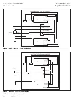
2.3.1 Installation Procedures for Top Entry
If bottom or side entry isn’t practical for the installation of the SPD
Max, top entry can be accomplished using the following steps.
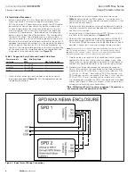
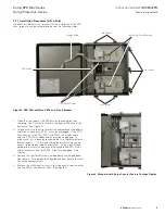
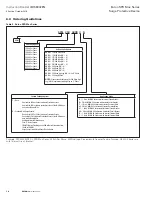
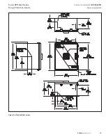
Figure 3. SPD Max with Two SPDs and Circuit Breaker
1. Open the front door of the SPD Max by loosening, but not
removing, the 7 latches that secure the door to the base of the
enclosure. See Figure 3.
2. To gain access to the wire termination compartment the display
cable for a single brick, SPD1, must be unplugged. If the SPD
Max contains two SPDs, SPD1 and SPD2, the display cable
and two SPD Status ribbon cables must be unplugged. In
either case, this is done by loosening the two Cable Hold Down
Bracket screws ~ 1/2 turn and sliding the bracket(s) up to gain
access to the ribbon cable connectors(s). Using a pair of long
nosed pliers carefully unplug the display cable and SPD Status
cable connectors from the SPDs, if they are equipped. See
Figure 3.
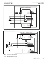
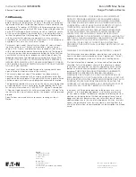
3. Remove the four Torx® screws holding down the hinged dead
front panels. Swing open the hinged dead front panels to access
the wiring compartments.
4. Remove the white neutral wire(s) from the neutral terminal block
and the SPD(s) and discard them. (See Figure 4)
Display Cable
Lid Latches
Cable Hold Down Brackets
Lid Latches
Lid Latches
SPD Status Cables
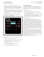
SPD Status
Figure 4. Standard with Surge Counter Feature Package Display