


9
Sonix Pbx Technical Manual
SONIX PBX TECHNICAL MANUAL
TM372 / A June 2022 www.eaton.com
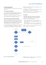
3.2 Overview of unit
Figure 1 – Front Panel Layout
Item
Description
1
Power On indication
2
Recording or playback status indications
3
Telephone connectivity mode
4
Message recording/broadcast aborted
5
Operational options
6
General power indications
7
User selection and control switch
8
User selection status
Table 1 – Front panel indications and controls
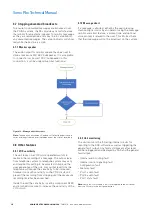
Figure 2 – Rear Panel Layout
Item
Description
1
A-side audio and data system connections
2
B-side audio and data system connections
3
Telephone interface connections
4
Message monitoring and abort connections
5
Isolated audio and key lines connections
6
+48Vdc input connection
7
General fault output connection
Table 2 – Rear panel connectors
3.2.1 Weight and dimensions
Un-packed:
up to 1.75 kg, 44 x 306 x 482 mm
(designed for 19” 1U mounting)
3.2.2 Power and utility
Voltage:
48 V dc
Current:
200 mA max consumption
R
Sonix Pbx
TM
LOCAL STATUS
POWER SUPPLY
OPERATIONAL
Fuse
Cancel
Zoned / Global
Source Select
Reset
DC PSU
2w
E+M
2w
Global
Message
Zoned
Message
Message
Cancel
Monitor
Active
Pbx
playback
Pbx
record
Power
8
7
6
5
4
3
2
1
Pbx I/P
MONITOR
A SIDE O/P
B SIDE O/P
48V
DC
I/P
+ -
Fault
O/P
N/C
Com
K1 K2 SCN A1 A2
I/O Bus A
I/O Bus B
A1 A2 SCN COM N/C
A1 A2 SCN K1 K2
A1 A2 SCN K1 K2
COMPLIANT
7
6
5
4
3
2
1
2-Wire connection
Screen
E&M connection (optional)
Push button connection
Screen
Loudspeaker connection
Keyline connection
Screen
Audio connection
Power connection
0Vdc (-)
48Vdc (+)
General fault connection
N/C
Com
Pbx I/P
Primary Unit ID 1
Secondary Unit ID 2+
2 wire
Telephone I/F
Pbx I/P
K1 K2 SCN A1 A2
K1 K2 SCN A1 A2


