Eaton SDR-WEXT Installation Manual Download Page 2

Page 2 


Table of Contents 

Installing the Siren 

2


Quick Reference 

4


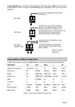
Connections to Other Control Units 

5


Connection Details 

6


TR 

6


ENG (Installer Mode) 

6


STR and BELL 

6


F-F and F-R and RST 

6


TF 

7


PCB Jumper Details 

7


SCB/SAB 

7


Trig Mon 

7


Tone Slct 

7


Time 

7


LED En 

7


Tmp Feed 

8


Fault and Tamper Monitoring 

8


Summary of Strobe Operation 

8


Maintenance 

8


Cable Recommendations 

9


Specifications 

9


Installing the Siren 

Step 1 

– Choose a Location for the Siren 

Choose a location that is: 

  Out of reach of intruders and vandals. 

  Easily visible for maximum deterrence. 

  Within the allowable cable distance 

(see 

Cable Recommendations

 on page 

9). 

Step 2 

– Open the Lid of the Siren 

1.  With the siren not yet fixed to the wall, 

open the hinged cover that gives 
access to the lid-retaining screw (see 
Figure 2). 

2.  Loosen the screw and open the lid. 

Step 3 

– Configure the Siren Jumpers 

1.  Remove the link/terminal cover (see 

Figure 2) by pushing the two retaining 

tabs to the side of the unit while lifting 
the cover. 

2.  Set all jumpers in the siren to the 

required positions (see

 Quick 

Reference 

on page 4). 

Step 4 

– Disconnect all Power 

Make sure that all power to the control unit 
is disconnected, including the backup 
battery. Also make sure that the battery in 
the siren is not connected. 

Step 5 

– Install Cabling 

Install all cabling between the control 
unit/expander and siren (see 

Cable 

Recommendations

 on page 9). Connect the 

cabling at the control unit/expander end, but 
leave the siren unconnected for now. 

Note:


To prevent water ingress, cables must enter 
the cable-entry hole at the siren (see Figure 
2) from below. 

Step 6 

– Attach the Siren to the Wall 

1.  Position the siren against the wall using 

the built-in spirit level to assist levelling, 
and mark all four fixing points. 

2.  Drill and plug the fixing points using the 

screws and plugs provided. 

3.  Pass wiring through the cable-entry 

hole. 

4.  Screw the siren to the wall. Use the 

spirit level and revolving guides to 
correct any misalignment. 

Step 7 

– Connect the Siren Wiring, 

Power Up and Close the Lid 

Note: 

The sounder should not activate 

during the following process. 

However, be 

prepared in the event that it does 
activate; make sure that any very loud 
noise produced cannot cause a fall.


1.  Connect all wiring to the siren (see


Quick Reference 

on page 4). 

2.  Connect the siren battery (see Figure 

1). 

Summary of Contents for SDR-WEXT

Page 1: ...to install 100 dB A sound output High power comfort LEDs High power LED strobes Selectable SCB or SAB mode Built in spirit level Self supporting lid for ease of installation Revolving fixing holes En...

Page 2: ...Reference on page 4 Step 4 Disconnect all Power Make sure that all power to the control unit is disconnected including the backup battery Also make sure that the battery in the siren is not connected...

Page 3: ...are using an i on or Menvier control unit you need to carry out the following for the siren a If you are using the ENG input Installer Menu Outputs Radio Wired Outputs Panel Exp nn nn output number Ty...

Page 4: ...to enable the comfort LEDs Time Choose the sounder cut off period 0V 12V BELL Trigger or output of type Siren STB STR or output of type Strobe Output of type Installer on Site Output of type Remote Se...

Page 5: ...BELL Aux B Aux B ADE T STROBE B D A Texecom C S B A D GE 270R TR STROBE EXT BELL BELL 12V BHO Risco Gardtec SCBP STB BELL BELL SCBA DSC Range ZONE PSM1 BELL BELL AUX Table 1 Connections to Other Contr...

Page 6: ...Return volt free terminals which are used to provide sounder and battery fault reporting to the control unit To enable sounder and battery fault reporting see Quick Reference on page 4 for connection...

Page 7: ...using an open collector output from another type of control unit and want to check for the presence of a 4k7 pull up temporarily connect a separate 4k7 resistor between the output and 0V if a 4k7 res...

Page 8: ...onitoring The siren monitors the following Tamper conditions All tamper conditions reported by the TR terminal see page 6 are continuously monitored The siren self activates on a tamper Battery voltag...

Page 9: ...nal Current Consumption 35mA quiescent current including battery charge and comfort LEDs 225mA in alarm current in SAB mode Sound Output 100 dB A IP Rating IP65 Strobe Frequency Double flash approx 1H...

Page 10: ...Page 10 NOTES...

Page 11: ...Page 11 NOTES...

Page 12: ...ONTENTS OF THIS DOCUMENT SHALL NOT BECOME PART OF OR MODIFY ANY CONTRACT BETWEEN THE PARTIES In no event will Eaton be responsible to the purchaser or user in contract in tort including negligence str...

Reviews: