


34008030EN/AD - Page 16
2. Installation
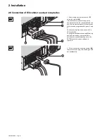
2.5 Communication ports
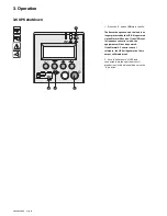
MX RT
provides 3 communication methods that can be used simultaneously:
◗
2 COM ports provide RS232 or USB communications using EATON SHUT protocol. Compatible with most power
management software applications available into the enclosed
Solution Pac
CD-Rom. Please, note that both ports
cannot be used at the same time.
◗
The output contact port is used for basic signaling or for protection of IT systems like IBM iSeries (formerly AS400)
and more.
◗
The slot is compatible with any EATON communication card (check
www.eaton.com
web site for the complete list
of compatible cards).
Connection to the RS 232 communication port
Connection to the communication port by relays (14)
(see page 8)
1 - Connect the RS232
(42)
communications cable to the serial port on
the computer equipment.
2 - Connect the other end of the
communication cable
(42)
to the RS232
(13)
communications port on the UPS.
The
UPS
can now communicate with
various EATON power management
application software. Please note that the
configuration software is included with
Personal Solution Pac
for Windows.
◗
Pin 1, 2: not used,
◗
Pin 3: remote Power Off signal (5 to 27 V DC, 10 mA max),
◗
Pin 4: operation on mains (not on battery),
◗
Pin 5: user common,
◗
Pin 6: operation on automatic by-pass,
◗
Pin 7: low battery,
◗
Pin 8: load protected,
◗
Pin 9: operation on battery.
n.o.: contact normally open.
n.c.: contact normally closed.
When the status is active, the contact between the common (Pin 5) and the relevant information pin is closed.
Output relays specifications
◗
Voltage: 48 V DC max,
◗
Current: 2 A max,
◗
Power: 62,5 VA, 30 W.
Example: for 48 V DC, Imax=625 mA
RS232
CONTACTS
RPO
PARALLEL
SWITCHED
GROUP 2
SWITCHED
GROUP 1
42
13
BATTERY
DETECTION
5 4 3 2
9 8 7 6
1
n.o.
n.c.
n.o.
n.o.
n.o.
common
14


