


14
User’s Guide P-164000628
P-164000628—Rev 05
33..44
EEaattoonn 99P
PX
XM
M U
UP
PS
S C
Coonnnneeccttiioonn D
Diiaaggrraam
m
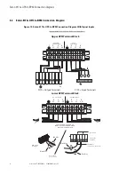
Figure 14. 9PXM UPS Connection Diagram with Signal Inputs
1 2 3 4 5 6
7
8
AC TO
UPS INPUT
AC FROM
UPS OUTPUT
L2
N L1
L2
N L1
1
2
3
4
5
6
7
8
L2
N L1
L2
N L1
AC TO LOADS
CABLES FROM UPS AND AC
INPUT/OUTPUT THROUGH BPM
BOTTOM ACESS PLATE
AC LINE INPUT
To Load
To Utility
L1
L2
N
L1
L2
N
9PXM Output Terminals
9PXM Input Terminals
(Install conduit
over signal wires)
BPM Signal
Terminals
** Set the value of “Signal Input 1 and Signal Input 2” through the UPS front display to “Normally Open”. **
White Wire
White Wire
Black Wire
Red Wire
Red Wire
Black Wire
Upper BPM Terminal Block
Lower BPM Terminal Block
Summary of Contents for Powerware 9155
Page 4: ...iv User s Guide P 164000628 P 164000628 Rev 05 Table of Contents...
Page 6: ...vi User s Guide P 164000628 P 164000628 Rev 05 List of Figures...
Page 8: ...viii User s Guide P 164000628 P 164000628 Rev 05 List of Tables...
Page 18: ...10 User s Guide P 164000628 P 164000628 Rev 05 Signal Wire Routing...
Page 28: ...P 16400062805 P 164000628 05...


