INSTALLING A REMOTE EMERGENCY POWER−OFF SWITCH
EATON
Powerware
®
225 kVA PDU Installation and Operation Manual
S
164201629 Rev D
www.powerware.com
4−2
5.
Remove the PDU cabinet interface entry conduit landing plates to drill or punch
holes (see paragraph A.4 on page A−39).
6.
Reinstall the interface entry plates and install conduit.
7.
To locate the appropriate terminals and review the wiring and termination
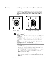
requirements, see Figure 4-1 and paragraph A.6 on page A−50 and paragraph A.7
on page A−55.
8.
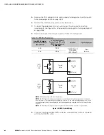
Route and connect the wiring as shown in Table 4-1 and Figure 4-2.
Table 4-1. REPO Wire Terminations
From REPO Station(s)
Switch Contact Block
(Either Block)
To Customer Interface
Terminal Board TB1 on the
PDU Universal Control
Board (UCB)
Wire Size
Tightening Torque
3 NO
TB1-5
Twisted Wires (2)
14–22 AWG
(0.75–4.0 mm
2
)
7 lb in
(0.8 Nm)
4 NO
TB1-6
NOTE
REPO switch rating is 24 Vdc, 1A minimum.
NOTE
The REPO switch must be a normally−open or normally−closed latching-type switch not tied into
any other circuits. The factory default configuration is set up for use with a normally−open switch. To use
a normally−closed switch, the configuration must be changed during setup by an Eaton Customer Service
Engineer
.
NOTE
The REPO switch wiring must be in accordance with NEC Article 725 Class 2 requirements.
5 (REPO)
PDU UCB
TB1
REPO
Switch
(NO)
Twisted
Wires
6 (Return)
3
4
5 (REPO)
PDU UCB
TB1
REPO
Switch
(NC)
Twisted
Wires
6 (Return)
1
2
Figure 4-2. REPO Switch Wiring
9.
If you are installing multiple REPO switches, wire additional switches in parallel
with the first REPO switch.
Summary of Contents for Powerware 225 kVA Three-Phase Power Distribution...
Page 141: ......
Page 142: ...164201629D 164201629 D...


