92
Eaton Power Xpert 9395 UPS Installation and Operation Manual 164201716—Rev 13
66..22
S
Siinnggllee U
UP
PS
S
A single UPS operates independently to support an applied load from the inverter, providing conditioned and
uninterruptible AC power to the critical load from the output of the module. During an outage, the inverter
continues to operate, supporting power to the load from the battery supply. If the unit requires service, applied
loads are transferred to the internal bypass, continuous-duty static switch either automatically or manually.
With the exception of a battery cabinet, no other cabinets or equipment are required for the single UPS to
successfully support its applied loads.
66..22..11
M
Mooddeess
The Eaton 9395 UPS supports a critical load in five different modes of operation:
NOTE
The Variable Module Management System and Energy Saver System modes are
mutually exclusive.
•
In Online mode, the critical load is supplied by the inverter, which derives its power from rectified utility AC
power. In this mode, the battery charger also provides charging current for the battery, if needed.
•
In Energy Saver System (ESS) mode, commercial AC power is supplied directly to the critical load through
the continuous static switch and transfers automatically to Online mode if an abnormal condition is
detected.
•
In Variable Module Management System (VMMS) mode, the UPS operates as a traditional double-
conversion UPS, but selectively shifts the load to fewer UPMs to increase the efficiency of the UPS.
•
In Bypass mode, the critical load is directly supported by utility power.
•
In Battery mode, the battery provides DC power, which maintains inverter operation. The battery supports
the critical load.
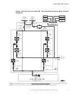
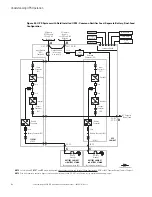
The following paragraphs describe the differences in the UPS operating modes, using block diagrams to show
the power flow during each mode of operation.
66..22..22
O
Onnlliinnee M
Mooddee
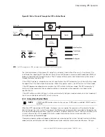
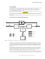
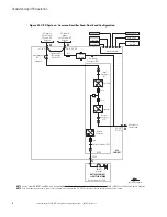
shows the path of electrical power through the UPS system when the UPS is operating in Online
mode.
During normal UPS operation, power for the system is derived from a utility input source through the rectifier
input contactor K1. The front panel displays “Online,” indicating the incoming power is within voltage and
frequency acceptance windows. Three-phase AC input power is converted to DC using IGBT devices to
produce a regulated DC voltage to the inverter. When contactor K2 is closed the battery is charged directly
from the regulated rectifier output through a buck or boost DC converter, depending on the system voltage and
the size of the battery string attached to the unit.
The battery converter derives its input from the regulated DC output of the rectifier and provides either a
boosted or bucked regulated DC voltage charge current to the battery. The battery is always connected to the
UPS and ready to support the inverter should the utility input become unavailable.

