background image

EATON 

Installation & Maintenance Instructions 

TM396 – XF-XP-XT LW UL ISS.A


5 | 

P a g e


2.0  Description 

The Series ‘X’ camera assemblies have been developed to meet the rigorous requirements of Flame proof 

and dust-ignition-proof electrical equipment for installation and use in hazardous locations found in the 

onshore and offshore, oil & gas and petrochemical installations. The units may also be used in marine and 

industrial hazardous environments. 
The housing enclosures and all external parts are manufactured entirely of AISI 316L stainless steel for low 

maintenance and protection from corrosion. 
Removable end covers are fixed to the body by five (5) M6 x 12 stainless steel hex cap screws. Cable entry 

cover is an M110 x 1.5 screw-fit cover. All fixings conform to the requirements of UL 1203. The 

weatherproof seal at the union between enclosures and covers is maintained using ‘O’ ring seals. 
The camera housings feature an internal sliding camera mounting rail, which is fitted with an internal 

heating element/de-mister, thermostatically controlled to maintain operating temperature, and ensure 

clarity of vision through the window. There is an optional integral window wiper mechanism. 
The viewing window is made with toughened glass, or in the case of the Thermal Imager and Dual Imager 

versions, is made from Infrared transparent material, which is factory fitted with a mechanical window 

guard. 

THE MECHANICAL THERMAL WINDOW GUARD MUST NOT BE REMOVED. 

There are three system types in the ‘Series X’ certified units; these are: 


XF: Fixed camera housings. 


XP: Pan & Tilt units with integral base section for cable connections. 


XT: Pan & Tilt units with integral base section for cable connection, and a secondary linked housing 

for an integrated illuminator. 

The XF fixed housings comprise a single tube section enclosure with either cable entries in the rear cover or 

in the side (model dependent). 
The XP and XT units have a single cable entry into the fixed base section, this prevents any trailing cables. 
The Series ‘X’ housings and pan/tilt units have been designed and certified to the UL 1203 Directive, with 

the following ratings: 

Class I Div 1 Groups B, C, D 


Class I Div 1 Groups A, B, C, D 

Class II Div 1 Groups E, F, G 


Class II Div 1 Groups E, F, G 

Class I Zone 1 IIB + Hydrogen 


Class I Zone 1 IIC 

-60°C to +70°C   


-20°C to +70°C 

T4 T135°C IP66/67  

Note

: T class and ambient temperature, is dependent on the assembly configuration and maximum 

internal power dissipation.  

*=T class T4A, T5, T6 

The project requirements and unit certification label must be checked by the installer before installation, to 

confirm that the product supplied is suitable for the intended installation zone and environment.  
Manufactured in accordance with  
UL 1203 Edn.5, CSA22.2 No30-M1986 Edn1 reaffirmed 2012, CSA C22.2 No25-1966 reaffirmed 2014, CSA 

C22.2 No 60065-03 Edn.1, UL60065 Edn.7. 

2.1 

Versions 

There are different camera options available within the range; these include Day/Night cameras with 

optional wiper, integral washer or external washer, thermal imager and dual camera day/night and thermal 

units. 
The range also includes options for HD IP cameras, digital fiber optic convertors and media convertors. 
Due to the large number of possible configurations, this manual only covers the standard installation of the 

units. 

Summary of Contents for OXALIS

Page 1: ...anual should be read and understood before attempting to connect or operate the equipment This manual should be kept for future reference This equipment shall be installed in accordance with the latest local national codes of practice and standards e g UL 1203 Edn 5 CSA22 2 No30 M1986 Edn1 reaffirmed 2012 CSA C22 2 No25 1966 reaffirmed 2014 CSA C22 2 No 60065 03 Edn 1 UL60065 Edn 7 Whilst every ef...

Page 2: ...nstallation 11 3 3 1 Sunshield Installation 11 3 3 2 Washer Nozzle Installation 12 3 4 Electrical Installation 13 3 4 1 Electrical Installation XP XT Integrated Pan Tilt housing assembly 13 3 4 2 XP XT Common Connection Examples 15 3 4 3 Electrical Installation XF Series Units 16 3 4 4 XF Series Common Connection Examples 17 4 0 Maintenance 18 4 1 Corrosion Protection 18 5 0 Labelling Marking 18 6...

Page 3: ...EATON Installation Maintenance Instructions TM396 XF XP XT LW UL ISS A 3 P a g e Amendment Record Issue Date Details of Amendment A 20 05 2021 First Issue ...

Page 4: ...nt is designed to satisfy the requirements of UL60065 7th Edition 2013 07 24 CSA C22 2 No 60065 03 2012 08 01 Safety Requirements ANNEX II of ATEX directive 94 9 EC 7 Be aware that aggressive substances may require extra protection of the equipment to maintain its integrity and explosion protection 8 The equipment may need additional means of protection if it is to be installed in locations where ...

Page 5: ...a housings XP Pan Tilt units with integral base section for cable connections XT Pan Tilt units with integral base section for cable connection and a secondary linked housing for an integrated illuminator The XF fixed housings comprise a single tube section enclosure with either cable entries in the rear cover or in the side model dependent The XP and XT units have a single cable entry into the fi...

Page 6: ...on and maintenance purposes we recommend the following hand tools Voltmeter Ohmmeter Torque wrench kit Set to 7 5Nm Hex Allen wrench bits of 5 4 3 1 5mm Spanners 5 5mm 8mm 10mm 13mm A F Screw drivers Standard and Phillips head Pliers Side cutting and long nose 2 4 Recommended Spares For Maintenance purposes we recommend the following spares OX10 00188 EX Base Cable Entry Seal Kit 50 8x3 53 O ring ...

Page 7: ...ing either side of the T body The camera housings must not be used for lifting To avoid damage to the unit DO NOT ATTEMPT to rotate the camera housings by hand The units should not be handled using direct contact with ferrous metal equipment see section 4 1 for details 3 2 Mounting Ensure the desired mounting surface can support four times the combined weight of the complete unit Do not stand or p...

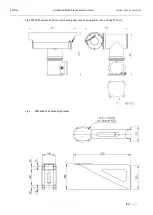
Page 8: ...ON Installation Maintenance Instructions TM396 XF XP XT LW UL ISS A 8 P a g e Fig 1 XP40VE Example XP Series unit showing base mount fixing points for an L Body PTZ unit Fig 2 BPW6500 Wall Mounting Bracket ...

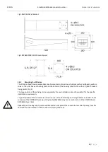
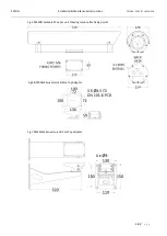
Page 9: ...four 4 M6 Threaded fixing points Fig 5 The type and size of these fixings to be supplied by the user installer and must be suitable for the specific installation requirements To gain flexibility of the cameras view direction one of the EATON range of fixing brackets is needed These comprise of the BFP00SW Swivel joint Fig 6 the BFW32SW Fig 7 or a combination of the BFW5000 and BFP00SW Figs 3 6 Dep...

Page 10: ...Maintenance Instructions TM396 XF XP XT LW UL ISS A 10 P a g e Fig 5 XF60VN Example XF Series unit showing mount plate fixing points Fig 7 BFW32SW Swivel Joint Pole Top Adaptor Fig 6 BFP00SW Swivel Joint Pole Top Adaptor ...

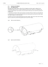
Page 11: ...re supplied with the camera system and should be positioned as detailed below To mount the sunshields first they must be positioned correctly and fixed with a Nylon spacer between the sunshield and the camera housing the M5 A4 Button head screws supplied must have the red fiber washer fitted before fixing the sunshield Fig 8 9 Sunshields can have four equally sized fixings at each corner Fig 8 or ...

Page 12: ...ioned to allow the cleaning fluid to reach the camera window when the wash command is sent The supplied washer nozzle brackets are specific to housing type and are delivered pre aligned for effective use Fig 10 When a wash command is sent to the camera the unit will move to a factory set position allowing the screen to be washed For non continuous rotation pan and tilt units and fixed housings the...

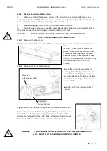
Page 13: ... internal objects and fittings WARNING THE BASE ENTRY COVER AND GLANDS SHOULD NEVER BE REMOVED WHEN THE UNIT IS ENERGISED WAIT 5 MINUTES AFTER DE ENERGISING 1 Always use colour coded conductors or other identification of conductors for ease of wiring and identification of function later 2 Keep a wiring diagram with the system for later use and reference 3 Provision is made for one or two cable ent...

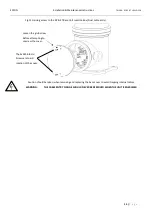
Page 14: ...unction Box Dual cable entry Caution should be taken when removing and replacing the base cover to avoid trapping internal cables WARNING THE CABLE ENTRY FLANGE SHOULD NEVER BE REMOVED WHEN THE UNIT IS ENERGISED Loosen the grub screw Before attempting to unscrew the cover The 2x M5 Btn Hd Screws are to aid rotation of the cover ...

Page 15: ...EATON Installation Maintenance Instructions TM396 XF XP XT LW UL ISS A 15 P a g e 3 4 2 XP XT Common Connection Examples Always refer to project specific drawings and information ...

Page 16: ... is fitted first take note of the parked position of the wiper arm and then remove it by loosening the M4 Cap Head screw that clamps to the wiper shaft Keep the wiper and nylon washer safe for refitting This is best done with the sunshield removed Fig 14 Removing the Front Window Cover Remove the front window cover by first removing the 5 x M6 Cap Head screws and then carefully extracting the cove...

Page 17: ...EATON Installation Maintenance Instructions TM396 XF XP XT LW UL ISS A 17 P a g e 3 4 4 XF Series Common Connection Examples Always refer to project specific drawings and information ...

Page 18: ...ery Inspection carry out the following Clean the exterior of the unit Check the O ring weather seals and replace if necessary Check and if necessary replace the washer nozzle Check and if necessary replace the window wiper blade assembly Use only Eaton approved spare parts 4 1 Corrosion Protection All external metal components are produced from 316L Stainless Steel however if the units are not cor...

Page 19: ...ation Maintenance Instructions TM396 XF XP XT LW UL ISS A 19 P a g e Certification label IIB Hydrogen Certification Label IIC Coding Class I Div 1 Group B C D Class II Div 1Groups E F G T135 C IP67 T Class T4 T5 T6 ...

Page 20: ...Kg depending on model Stand alone housing 12 22Kg depending on model Mounting Pan Tilt with housing 4 x M10 Cap Head screws on 182mm PCD Standalone housing Depending on mounting brackets Supply voltage 24VAC 50 60Hz or 100 to 230VAC with integral transformer Power consumption Max 120 Watts depending on model Cable Entry Options NPT thread or NPT thread using a suitably certified reducer and depend...

Reviews: