INM831B Rev 4
1
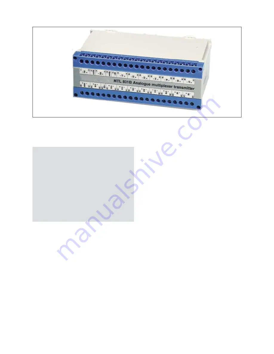
MTL831B
IS analogue multiplexer transmitter
INM831B Rev 3
1
ABOUT THIS MANUAL
The purpose of this manual is to provide the user with information on
the installation, connection and configuration of the MTL831B
analogue mutliplexer transmitter.
1.1
Related documents
This manual does NOT cover the connection or configuration of the
MTL838B-MBF receiver. For details of this item consult:
INM838B-MBF.
Additional application information is available in:
AN9010
.
1.2
Product description
The MTL831B analogue transmitter can transfer a number of
hazardous area input signals to the safe area down a data highway
consisting of a single twisted pair cable. It is intrinsically safe and can
therefore be mounted in Zone 0 hazardous areas or Class I, Division
1 hazardous locations.
The MTL831B can monitor up to 16 inputs from THC or millivolt
sources or up to 15 inputs from 2, 3 or 4-wire RTDs.
Two (i.e. dual redundant) data highway outputs are provided that can
carry both signal and power over distances up to 3km, depending on
the application, the cable and the (noise) environment - see Section
4.4. The highway cables can be simple twisted-wire pairs or pairs of
wire within an IS multi-core cable.
Modbus
®
is a registered trademark of Schneider Automation Inc.
At the other end of the data highway, MTL838B-MBF receivers are
used to translate the information transmitted from the MTL831B. The
MTL838B-MBF provides a Modbus
®
serial data output representation
of the inputs together with status information.
When the MTL831B transmitter is mounted in the hazardous area,
each data highway must be protected by an MTL3052 digital isolator
mounted in the safe area.
2
GETTING STARTED
Installation of the MTL831B multiplexer transmitter is divided into
three main topics.
Mechanical Installation
- how to mount the MTL831B and
how it may be fitted into our enclosure.
Electrical Connections
- the sensor and highway
connections. If units are installed in our enclosures, it details any
special wiring arrangements.
Configuration
- the address and input mode selection by the
setting of internal switches.
Note
: A new user might find it helpful to set up the system, or a
simple version of it, in an indoor test area to gain familiarisation
before undertaking installation on site.
3
MECHANICAL INSTALLATION
3.1
Location
The MTL831B can be installed in either safe or hazardous areas
(including Zone 0 or Division 1) depending upon the requirements of
the application.
3.2
Mounting options
The unit can be mounted on T-section DIN-rail or onto a flat surface.
Eaton has a range of enclosures - ENC8, ENC8-SS, ENC83 or
ENC83-SS - to provide suitable IP67 protection if the transmitter is
located in an exposed area.
3.2.1
Mounting on T-section DIN-rail (Figure 1)
Hook the side opposite the central mounting clip onto standard 35mm
DIN46277 T-section rail and push downwards until the unit clicks into
place.
To remove, ease the central clip below the base of the unit outwards
(with a screwdriver) and unhook the clips on the other side.
MTL831B transmitter and MTL838B-MBF reciever
"
Cautionary Note
: In common with all other electrical apparatus
installed in hazardous areas, this apparatus must only be installed,
operated and maintained by competent personnel. Such personnel
shall have undergone training, which included instruction on the
various types of protection and installation practices, the relevant
rules and regulations, and on the general principles of area
classification. Appropriate refresher training shall be given on a
regular basis. [See clause 4.2 of EN 60079-17].
This instruction manual supplements the requirements of nationally
accepted codes of practice, for example, IEC/EN 60079-14 in
Europe and the National Electrical Code, combined with
ANSI/ISA-RP 12.12 in the USA. All installations should comply with
the relevant sections of these codes.
In addition, particular industries or end users may have specific
requirements relating to the safety of their installations, and these
requirements should also be met".


