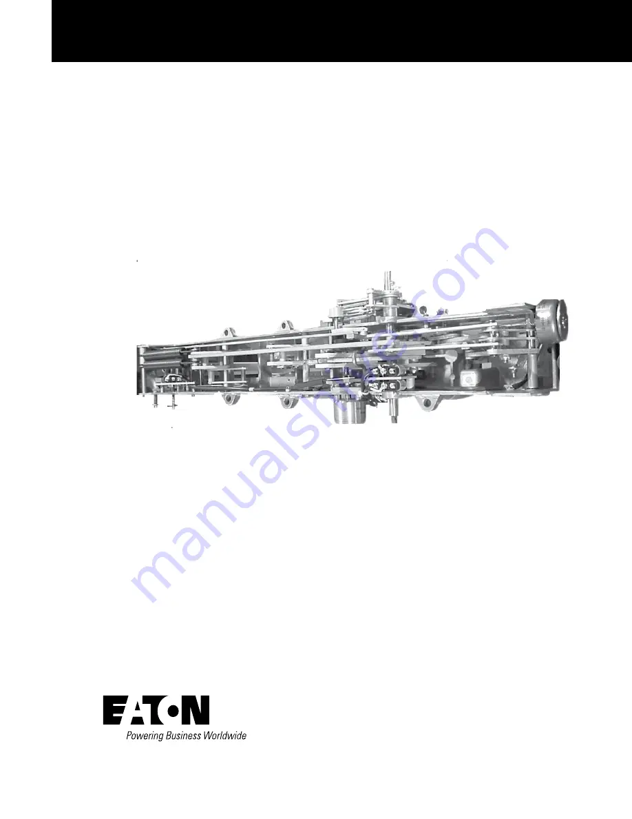
Mercury switch to microswitch retrofit kit KA349WE installation
instructions
COOPER POWER
SERIES
Reclosers
MN280022EN
Effective October 2015Supersedes S280-40-10 April 2014
Page 1: ...Mercury switch to microswitch retrofit kit KA349WE installation instructions COOPER POWER SERIES Reclosers MN280022EN Effective October 2015 Supersedes S280 40 10 April 2014...
Page 2: ...FITNESS FOR A PARTICULAR PURPOSE OR MERCHANTABILITY OTHER THAN THOSE SPECIFICALLY SET OUT IN ANY EXISTING CONTRACT BETWEEN THE PARTIES ANY SUCH CONTRACT STATES THE ENTIRE OBLIGATION OF EATON THE CONTE...
Page 3: ...duction 1 Handling and storage 1 Quality standards 1 Additional information 1 INSTALLATION Reposition contact bar 3 Disconnect terminal wires 3 Remove microswitch switch SW1 4 Remove mercury switch SW...
Page 4: ...hen working around high voltage lines and equipment and support our Safety For Life mission Safety information DANGER Hazardous voltage Contact with hazardous voltage will cause death or severe person...
Page 5: ...the carton for signs of damage Unpack the kit and inspect it thoroughly for damage incurred during shipment If damage is discovered file a claim with the carrier immediately Handling and storage Be ca...
Page 6: ...SW1 Main Shaft Grommeted Cable Exit Hole and Terminal Block Rotary Solenoid Plastic Cable Retainer Switch SW2 Handle Shaft Yellow handle manual trip shaft Contact Position Indicator Shaft H Bracket S...
Page 7: ...at points indicated in Figure 2 1 Remove C rings from contact bar retainer pin at trip solenoid end of mechanism and discard 2 Note position of any washers then remove and save them 3 Slide pin aside...
Page 8: ...ordance with all federal state and locally approved mercury disposal guidelines and regulations Figure 6 Removing switch SW3 from main shaft Figure 7 Springs and retaining pins Remove mercury switch S...
Page 9: ...lations 10 Scribe new handle shaft assembly Item 3 to mark orientation of cam and lever to shaft and shaft to frame Carefully remove roll pins cam and lever from new shaft Figure 9 Figure 10 Switch SW...
Page 10: ...itch SW2 4 Place cable over spacer near cable hole then securely tighten assembly to frame Use the two smaller spacers Item 4 machine screws Item 5 and self locking elastic stop nuts Item 6 to attach...
Page 11: ...ing retaining pin through the two large springs spacers and new C rings Item 21 Tighten C rings 4 With H bracket disengaged gently push down on switch SW2 until hearing a click as switch contact encou...
Page 12: ...ave roll pin 7 Slide main shaft aside to gain clearance for removing old microswitch cam Note orientation of cam on shaft Remove and discard cam Install new cam for SW1 1 Slide new switch cam Item 15...
Page 13: ...new cable retainer in the same position used by the old one 5 At the terminal block make the following connections refer to Figures 5 and 27 for terminal identification A Switch SW1 connect leads to...
Page 14: ...2 10 KA30090019 ALUMINUM SPACER 2 11 7215 15 110137A SLOTTED RD HD MACH SCR 10 24 UNC 2A 2 12 KA20200013 ELASTIC STOP NUT SS 10 24 2 13 9011 32 010000A EXTERNAL TOOTH LOCKWASHER 10 PL F 2 14 KA2048050...
Page 15: ...t review its positioning If positioned correctly review switch terminal and terminal block connections If all connections are correct check switch to make sure it actually opens and closes as its arm...
Page 16: ...ited States Eaton com cooperpowerseries 2015 Eaton All Rights Reserved Printed in USA Publication No MN280022EN KA2048 506 Rev 04 Eaton is a registered trademark All trademarks are property of their r...